I made(*) this tiny remote control for Sony Alpha cameras.
It can do what other camera remotes do, and I jam packed it with other weird features, features that I would like to see baked into the actual camera’s firmware.
I made(*) this tiny remote control for Sony Alpha cameras.
It can do what other camera remotes do, and I jam packed it with other weird features, features that I would like to see baked into the actual camera’s firmware.
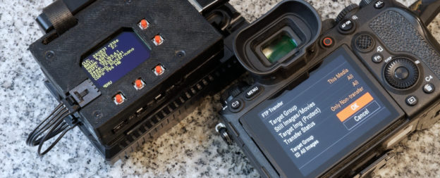
This is a tool made to transfer and backup photos from a professional camera while in-the-field. Built with a Raspberry Pi 4 (other Pis will work too, it’s all just Python code), using Wi-Fi for file transfers and USB disks for file storage, powered by batteries.
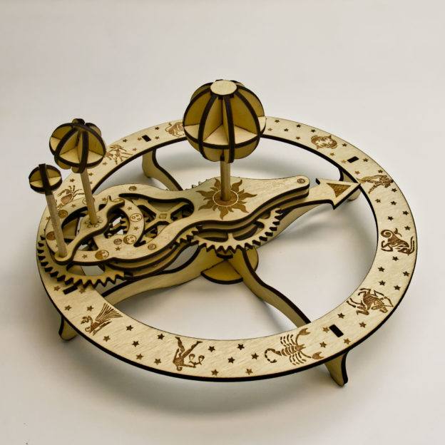
I’m having so much fun with my new Beamo laser cutter! I designed and made this wooden orrery with my Beamo. It’s a mechanical toy that depicts the position of the Earth and Moon as they orbit each other and the Sun, with artwork showing the moon phases and Zodiac. See more pictures and animation:
It’s nearly Christmas again! I’ve started to learn a new craft, an ancient one, and started to mix it up with modern technology.
Behold, stained glass suncatcher with embedded LEDs
This is essentially black magic to most glass artists and a huge “duh” moment to all the makers and engineers. I’ve been asked to teach how this is done…
I’ve had some fun with photogrammetry recently and wanted to try out other techniques for 3D scanning. I’ve actually sort of accomplished S.L.A.M. during a hackathon using the PlayStation 4 camera and the Xbox One Kinect already, but I wanted something portable! With the new Raspberry Pi 4 debuting this year, I can finally accomplish this… sort of…
This is a mineral oil submerged computer. Mineral oil is a liquid that looks and behaves like water but does not conduct electricity, hence why it is safe to run electronics inside it. The mineral oil also aids to control the temperature of the entire system, by soaking up and removing heat away from hot components like the CPU.
You might have already seen my first computer, which was also an aquarium computer. Something mighty unfortunate happened to it… This new aquarium computer is built with all the lessons learned from the first. Please continue reading to find out the details
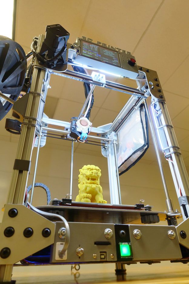
I finally did it, I designed and built my own 3D printer. This is in no way “the best 3D printer”. Instead, this was an epic and nightmare project that exercised my ability to engineer and build my own CNC machine. Along the way, I figured out what I did well and what I did badly, mistakes were made and sometimes fixed, even ignored.
This 3D printer is named Haphaestus. This wasn’t some kit that I purchased and put together, this wasn’t some tutorial I downloaded and followed. I designed almost everything about this printer and built it with tools I own and a waterjet cutting service. The only application specific parts I didn’t design are the Duet controller circuit and the E3D Titan parts.
NOTE: This is not an open source project where I will let you download a few files so you can build one yourself, trust me… you don’t want to. It’ll be a logistical nightmare to just organize the files and BOM to the point where it is useful to anybody else.
This page will be dedicated to recording my experiences and analysis of the first 3D printer I have ever designed and built all by myself.
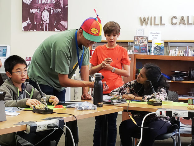
I spend my Saturdays volunteering at a public library makerspace, the South San Francisco Public Library. I help people operate a few 3D printers, a CNC mill, vinyl cutter, etc. While preparing for my annual RoboGames entry, I thought it’d be cool to teach the library’s patrons about robotics.
I designed a robot kit, partly 3D printed, with electronics that has to be soldered, and running with an Arduino Nano. The three classes are for 3D CAD modelling, soldering, and programming.
The robots are designed to be cheap enough for the library to actually give away. All of my courseware is open source, hosted on GitHub. A lot of the tools and parts were donated by people I know in my professional circles.
Here’s a link to the class content: click here
This blog post is about what I observed, what I did right, what I did wrong.
It’s that time of year when we think about gift giving. I decided to design a dome shaped box that opened with moving curved doors.
(dear iPhone users, sorry if the videos don’t work for you, please consider upgrading)
Keep reading for more pictures and a full tutorial teaching you how to create this in CAD.
This is the next step in my mission to make my car function 7 years newer and feel like a jet cockpit.
(click here if the above video isn’t loading)
I wanted a HUD, Heads Up Display to my car. The main purpose is to let me keep my eyes on the road and still be aware of my speed without looking down, hence “heads up”. This idea has been used in fighter jets for decades now.

I do not like any of the other ones on the market today, they all try to do “too much”. I wanted something more simple and elegant.
My design is a simple RGB capable individually controllable LED strip that reflect off my windshield.
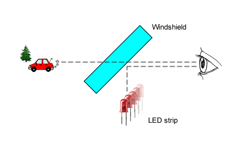
I used the “DotStar” from Adafruit Industries, which uses APA102 LEDs. The brain is a Teensy 3.2, which is connected to my car’s CAN bus via a OBD-II connector (the diagnostic port that you can read the engine computer from).

It is programmed to have three different modes: voltmeter, tachometer, and speedometer. The mode switching is “context aware”: When the car is moving, the mode changes to speedometer. If I rev the engine Continue reading
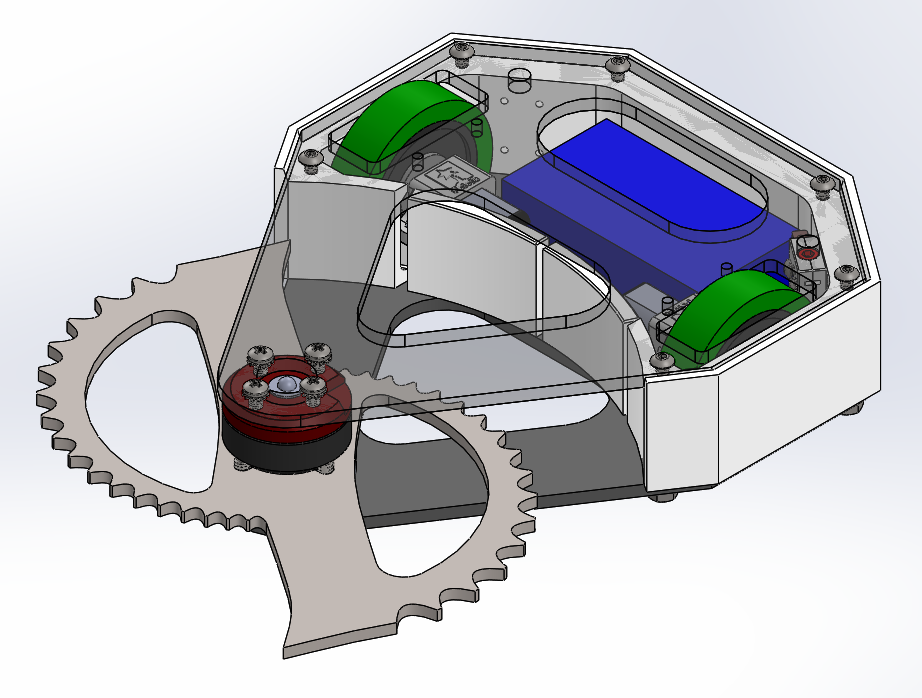
My 2018 competitor, with a titanium horizontal blade from FingerTech Robotics. I felt like rebuilding a drum spinner twice is too boring so gotta change up the weapon choice every year.
https://www.youtube.com/watch?v=jogX5dcA4ak
I was the winner of that fight because of the driving I did after my blade broke off. My radio is a FrSky Taranis Q X7 and it has adjustable curves for everything, so I actually had better driving control, better than most other competitors.
The steel shaft of the motor is the problem, apparently a hollow steel shaft isn’t hard enough to handle the impacts. The next video shows the second time the motor shaft broke. I did actually stick a #4-40 steel bolt into the hollow part, it may have made the problem worse, this time instead of just the shaft snapping, the entire plate holding the bearing shattered.
https://www.youtube.com/watch?v=BD62NHoWiC4
Just dumping media here
https://www.youtube.com/watch?v=Y5YiNv0Xkjc
Major Components:
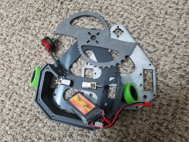
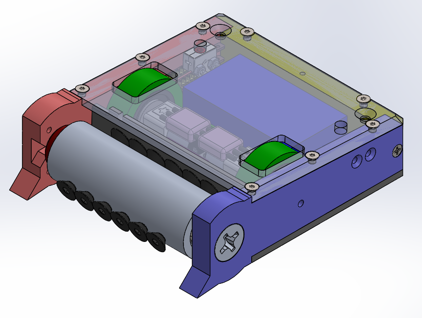
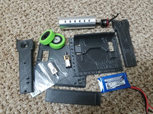
Designed as a replacement for Shrapnelly. Shrapnelly is almost impossible to repair, so Hells Bells is designed with a 3D printed nylon-CF body and totally off-the-shelf electronics. Currently a work-in-progress.
We did it, we said we were going to win and we did. We built something so technologically beautiful that Elon Musk himself crowned it the most innovative of them all.
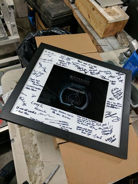
I am proud to have served on a team where the exact combination of passionate people was key to achieving our success. Every ounce of effort mattered, every single nut tightened, every single wire connected, every word spoken. Thank you all for standing beside me through it all. You are all amazing, and no matter how little you came in with, I hope working together helped you learn, and set yourselves up for a better future.
This is my first ever combat robot! 454 grams (1 lb American Antweight class). It has a spinning drum weapon.Body is made of Garolite, with titanium skirts mounted on hinges (parts are cut on my Nomad 883 Pro, and some 3D printing). The drum weapon is CNC lathed aluminum with a brushless motor inside. The electronics is all custom built, utilizing the 802.15.4 radio integrated in the ATmega256RFR2.
https://www.youtube.com/watch?v=krAhKgzNm9M
Want more details? Continue reading
I 3D printed a very durable peristaltic pump. It is capable of pumping very thick liquids at as much pressure as the tube can handle. It is durable because it is printed at 100% infill at high thicknesses and uses steel ball bearings. It is capable of such strength because it is using a massive 12V DC brushed motor that has a 150:1 gear ratio metal gear box, which means several kilograms of torque.
https://www.youtube.com/watch?v=oEmSM0tHnzU
For design files and more details, please continue reading.
http://youtu.be/ftLXenKbBOI
This project won 2nd place in this Reddit contest about functional 3D printed projects. Thank you very much to ToyBuilder Labs for being the sponsor.
You want files? Click Here. I hosted the files on YouMagine, and I provided the STEP file format, which you should be able to open with most 3D modeling software. So if you want to change the design for 3.5″ drives, or chose another cartridge shape, you can!
NOTE: the dimensions of the fake NES cartridge I used are not the same dimensions as genuine NES cartridges, so genuine cartridges will not fit in this project, and the fake cartridges will not fit inside a genuine NES deck.
My trusty laptop is showing its age. 8 GB of RAM is not enough for the amount of 3D stuff I do now, and it can’t run the latest games at all any more. Since I got a full time job now (instead of a constantly travelling student), it’s time to get a desktop PC (first PC build, yay). But the process of building a PC is pretty boring, it’s just an exercise of picking out compatible parts for the right price. I decided to make it slightly more interesting by submerging the entire computer in a fish tank full of mineral oil.
http://youtu.be/EAH_orqEp64
UPDATE March 2015, I added a funny naked HDD activity indicator
Some pictures from the build process
Intel i7 4790S, Nvidia GTX 970, H97M chipset, Corsair CX600M. Built onto a polycarbonate tray that is then dipped into a fish tank full of mineral oil. Fancy features like bubbling treasure chest, NeoPixel LED strip, oil pump+radiator, temperature monitoring, removable SSD.
(part list? fine… here… these are not the prices I paid but here it is http://pcpartpicker.com/user/frank26080115/saved/HFDmP6)
Comments and questions are welcome, I would love to chat with you!
Reddit posts, please upvote: http://www.reddit.com/r/battlestations/comments/2pdd3q/aquarium_computer_mineral_oil_submerged_details/ and http://www.reddit.com/r/buildapc/comments/2pdeak/build_complete_aquarium_computer_mineral_oil/
Hi Hack a Day visitors, small correction: there’s 32 GB of RAM, I just didn’t put the same item twice in the part list.
3D printed using my Ultimaker2 and many colors of PLA plastic at 100% in-fill. It is my first design, featuring folding arms, tucked away electronics, and anti-vibration mounted flight controller. It is designed to be friendly with FDM 3D printers, employing some special techniques. The frame is extremely strong.
http://youtu.be/z2xI3y_h1w4
I need more practice. I need to buy a few more propellers and few more batteries as well so I can practice for longer.
Flight controller is a Continue reading
The Ultimaker2 3D printer has a problematic filament feeder mechanism assembly. When the filament is stuck and the feeder motor turns, it can grind away the filament, causing a gouge in the filament. The gouge makes the problem worse since the tensioner bearing will force the gouge into the feeder’s knurled wheel more, causing even more grinding. This jam happens frequently because sometimes even if the temperature sensor reports that the print head hot end has heated up, the plastic hasn’t melted yet and can’t move yet.
The Ultimaker2’s feeder design is both beautiful and disappointing. It is beautiful in the sense that is is symmetrical and compact. If you had a dual extruder, you can use the same feeder mechanism for both feeders, cutting down on manufacturing costs. But it is impossible to disassemble without removing the stepper motor because the same 4 screws that holds the feeder together also holds the stepper motor in place. If you attempt to open the feeder mechanism to clear a jam, the motor will fall off. The motor is also covered by a metal casing so you need to remove the casing as well. This is very annoying.
There is no other way to move the tensioner bearing because the design is so compact and the spring is tight. There is no other way to remove the feed tube either.
What I needed was a feeder mechanism that can be opened up without removing the stepper motor, and also allow the tensioner bearing to be moved out of the way easily. I came up with the following design:
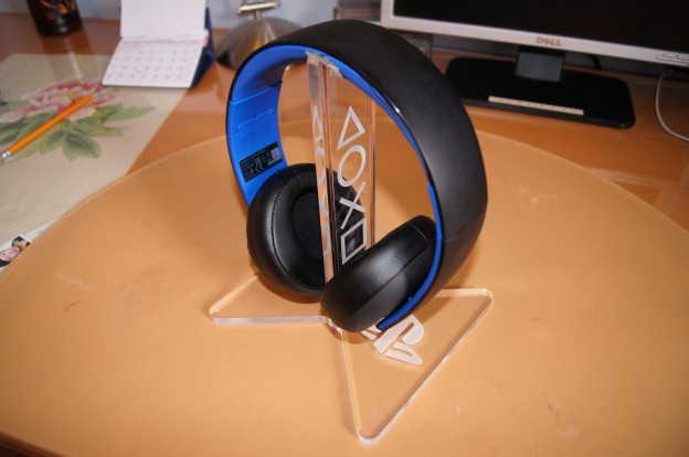
I have a PlayStation Gold wireless headset, for chatting with people I play video games with. It usually recharges via a USB cable but I wanted a recharging stand for it, so that the USB connector does not suffer from wear-and-tear and I don’t have to worry about managing yet-another-USB-cable.
http://youtu.be/vFXE_K8yG2w
More pictures below Continue reading
I like playing shooter games on PC but my laptop is too weak to play them. Game consoles do not support USB keyboards and USB mouse, they only support gamepads. Gamepad controls are not suitable for shooter games, using a keyboard and mouse is much more comfortable for gameplay.
I designed a circuit that features a microcontroller and USB hub. The keyboard and mouse plugs into the USB hub, and then the microcontroller takes the data from the keyboard and mouse, translates them to the data format used by the PlayStation 4. It does the translation in a way as though the mouse was the right thumbstick, and the keys are mapped to buttons (the WASD keys are mapped to the left thumbstick).
I wanted to share this story because I am very happy that I finally managed to get this far! Anybody who is attempting this and thought it was impossible to do can now breath a sigh of relief because it definitely can be done.
I have already accomplished a similar project that worked with a PS3 (UsbXlater), something that connected to the PS3 via USB that translated keyboard and mouse data format to gamepad data format.
Once the PS4 launched, I reversed engineered the USB protocol used by the DualShock, and then attempted the same technique. But… Continue reading
This circuit is a STM32F2 chip with a USB host interface and USB device interface. The original goal of this project is to allow me to play Playstation 4 games using a keyboard and mouse (as opposed to using a gamepad, because the PS3/PS4/Xbox360/XboxOne do not support keyboard and mouse directly in games).
http://youtu.be/W8PGDY_7yuQ
This device has many possible uses…
http://www.youtube.com/watch?v=vnMC7wVD6IM
Please watch the full video (8 minutes), which explains the project in full.
I designed, built, and programmed almost every bit and piece of this project. I did not design light tube and lens assembly. This project involved a broad range of my skills: electronics, wireless communication, mechanical 3D CAD, thermal design, design for manufacturing, etc. I did this project while still studying in university.
Dentists often use head-mounted lamps, but to operate these lamps, they need to remove their gloves first because their gloves is usually covered with saliva and blood. iDOC360 hired me to make a system that is controlled using hand gestures, so the dentists do not need to remove their gloves to operate it.
A simple adjustable constant current dummy load, with digital readout and USB data logging.
Inspired by the dummy load made by Dave from the EEVBlog. I decided I wanted one because I work with a lot of battery powered designs and it’d be nice to have a simple way of testing a battery or power supply in terms of capability, capacity, and heat. It features a 2 line voltage and current reading, a rotary encoder as the user input to adjust the current setting, and USB data logging (plus bootloading). There are more neat features, please watch the video.
http://youtu.be/WCu5cJbpQgQ
Here are some pretty pictures: (Imgur Album)
I am currently working with Adafruit on Trinket stuff, because of my experience with USB and V-USB. Recently I wrote a bunch of simple tutorials and libraries for Trinket:
I have many projects, but some of them are just short code libraries and snippets that I don’t want to allocate an entire blog post for. For more information on each, visit the link and read the “readme” provided.
LufaUsbAspLoader, a USB bootloader that combines LUFA and USBaspLoader, so it can be used in low-speed USB devices
Arduino-UsiSerial-Library, written mostly for Trinket, works for all ATtiny microcontrollers with a USI
Adafruit-Trinket-USB, a small collection of libraries that enable USB capabilities for Trinket, and other ATtiny V-USB projects
This is a LED pocket watch. It has 12 LEDs to show the hour, 60 LEDs to show the minute, and 60 LEDs to show the second. The LEDs are arranged in three rings. There is a button on the top to activate the pocket watch, and a button on the back to change modes and settings.
http://www.youtube.com/watch?v=1YD8rQ0h6oI
The battery is a rechargable lithium ion coin cell battery and it is charged from a micro USB connector. The battery life depends on how heavily the pocket watch is used, but if you leave it alone, it is estimated to last several months. There is a low battery indication feature. This pocket watch also feature a buzzer and a vibration motor, which are used for the alarm feature, and the motor causes a short “tick” as each second passes by. The pocket watch is constructed of a PCB, two pieces of laser cut clear acrylic plastic, and a 3D printed casing.
Click Me!! More instructions, pictures, animations, and videos.