It’s nearly Christmas again! I’ve started to learn a new craft, an ancient one, and started to mix it up with modern technology.
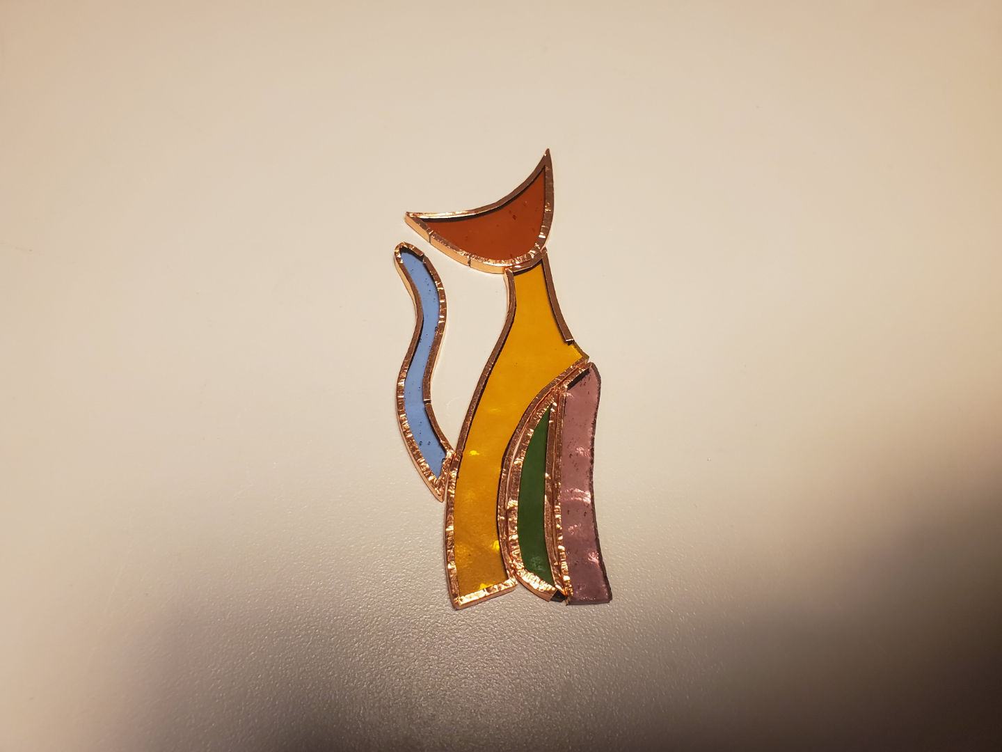
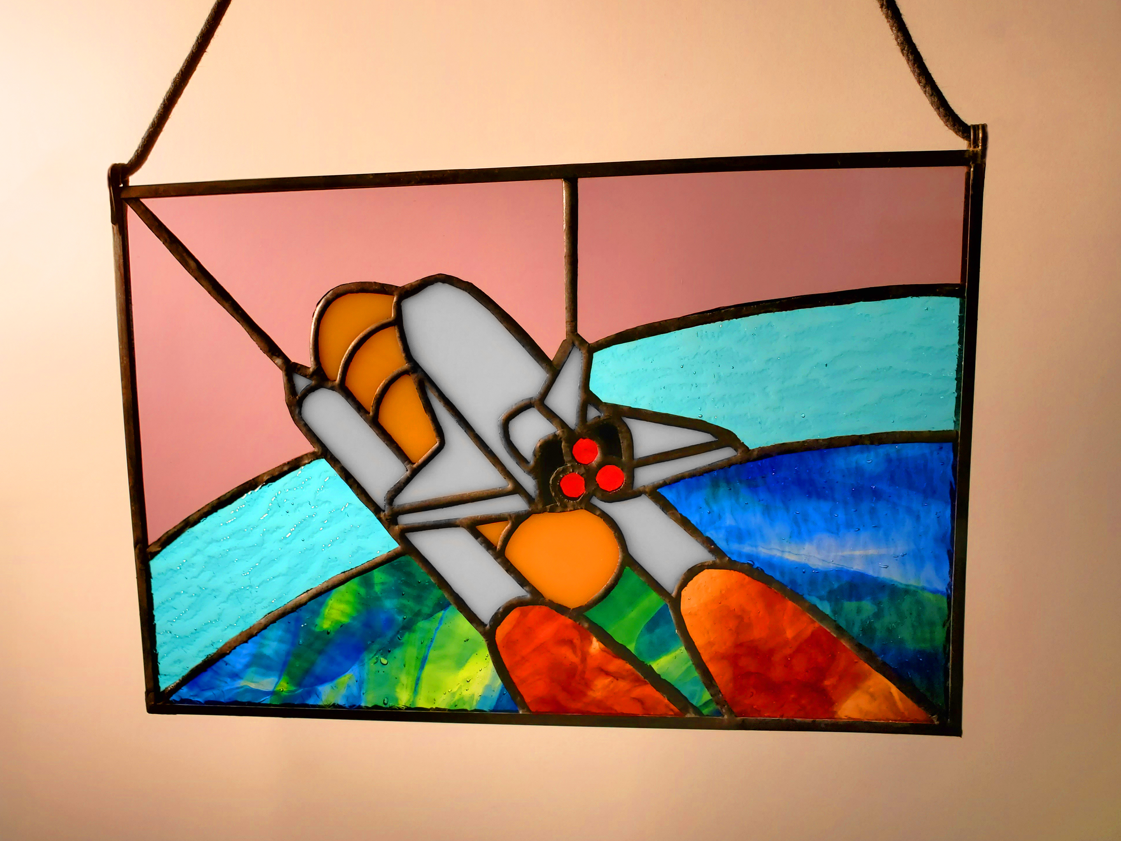
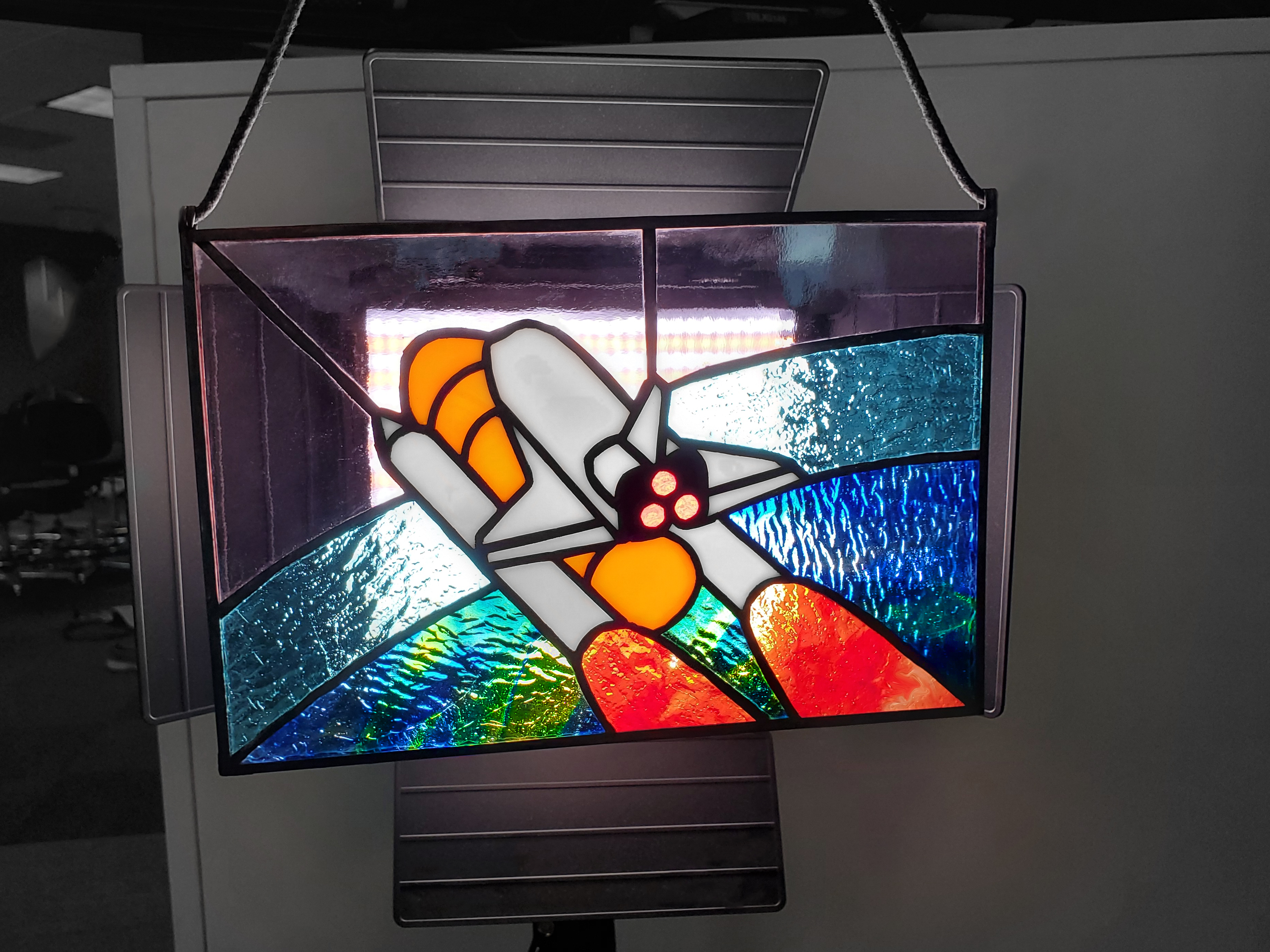
Behold, stained glass suncatcher with embedded LEDs
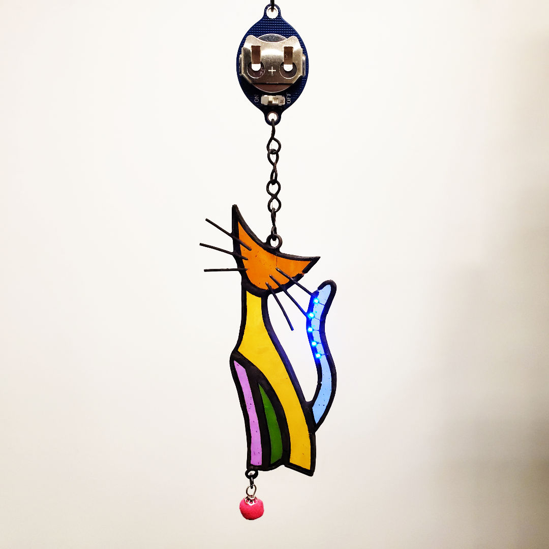
This is essentially black magic to most glass artists and a huge “duh” moment to all the makers and engineers. I’ve been asked to teach how this is done…
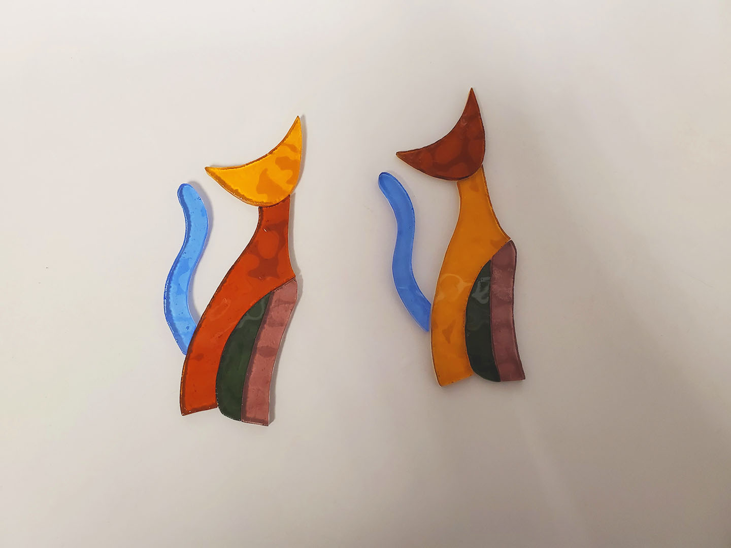
Just a teaser preview of my second project

Before I start talking about the geeky part, I’d like to summarize the basic steps in making a basic piece of stained glass artwork like this:
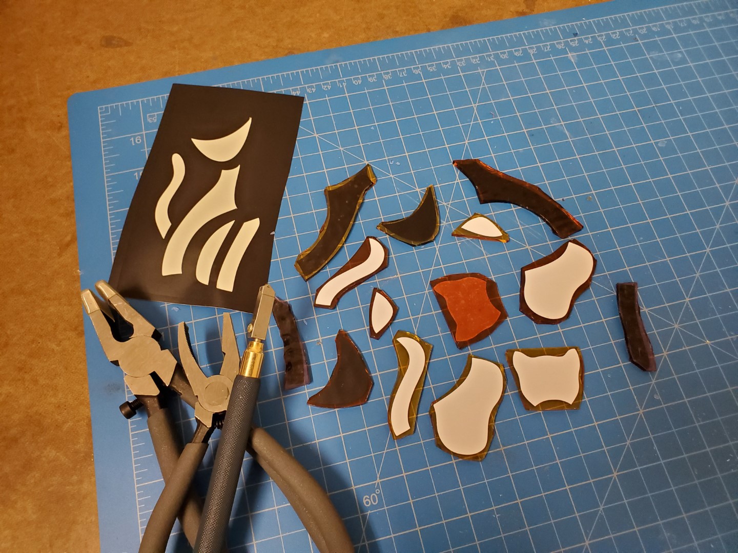
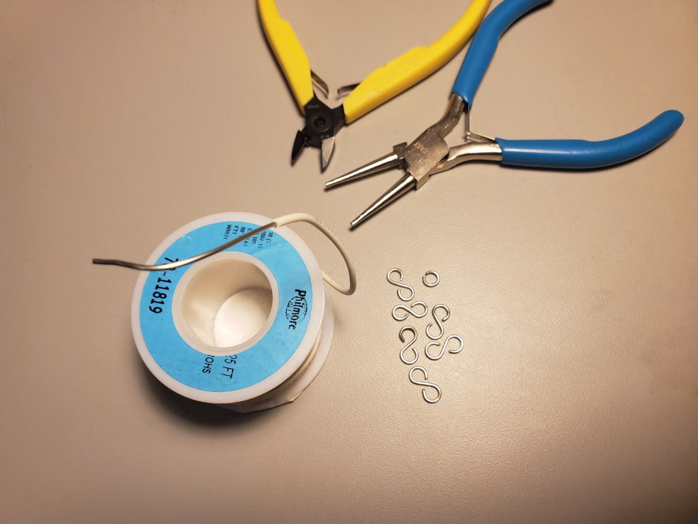
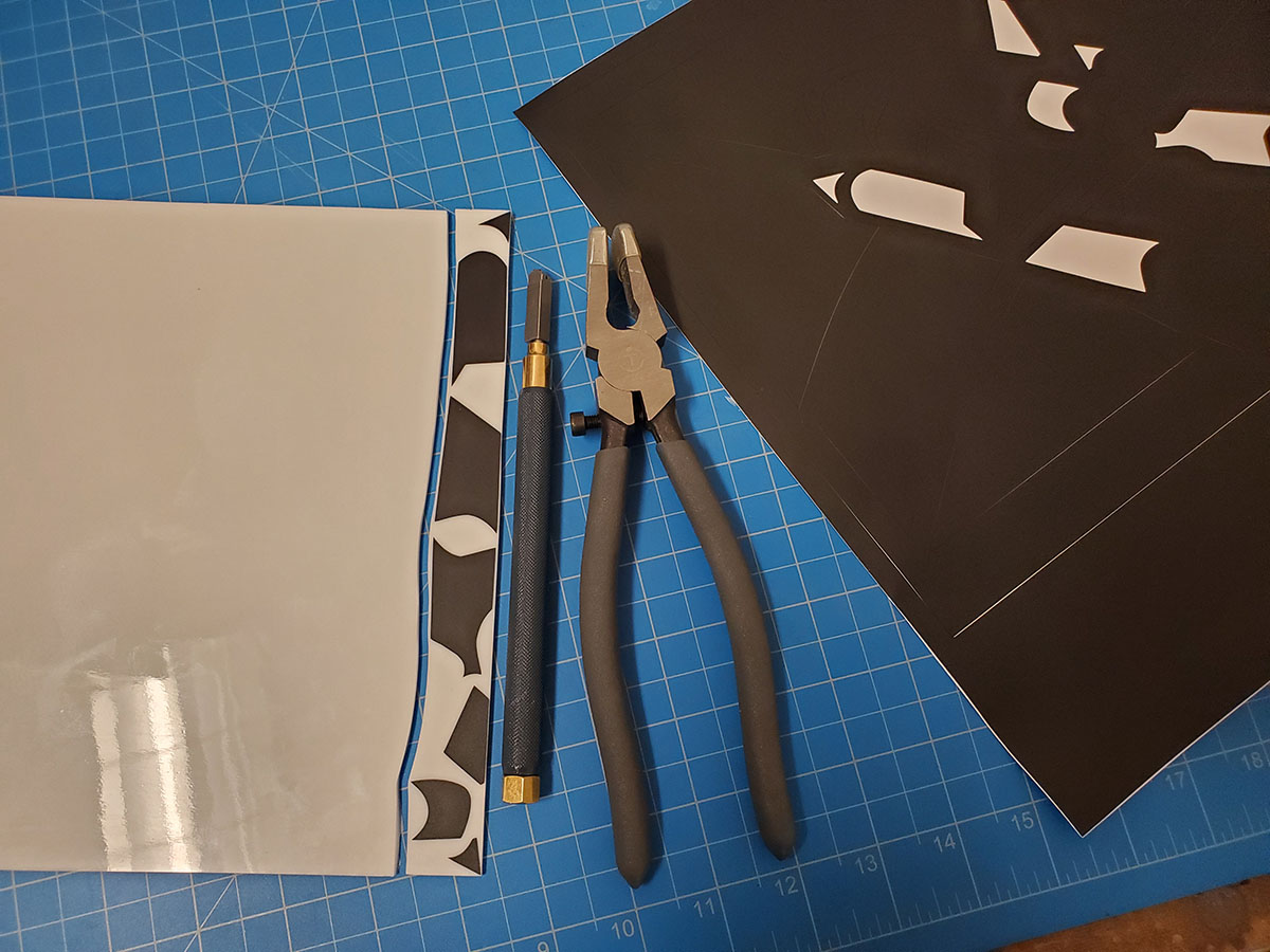
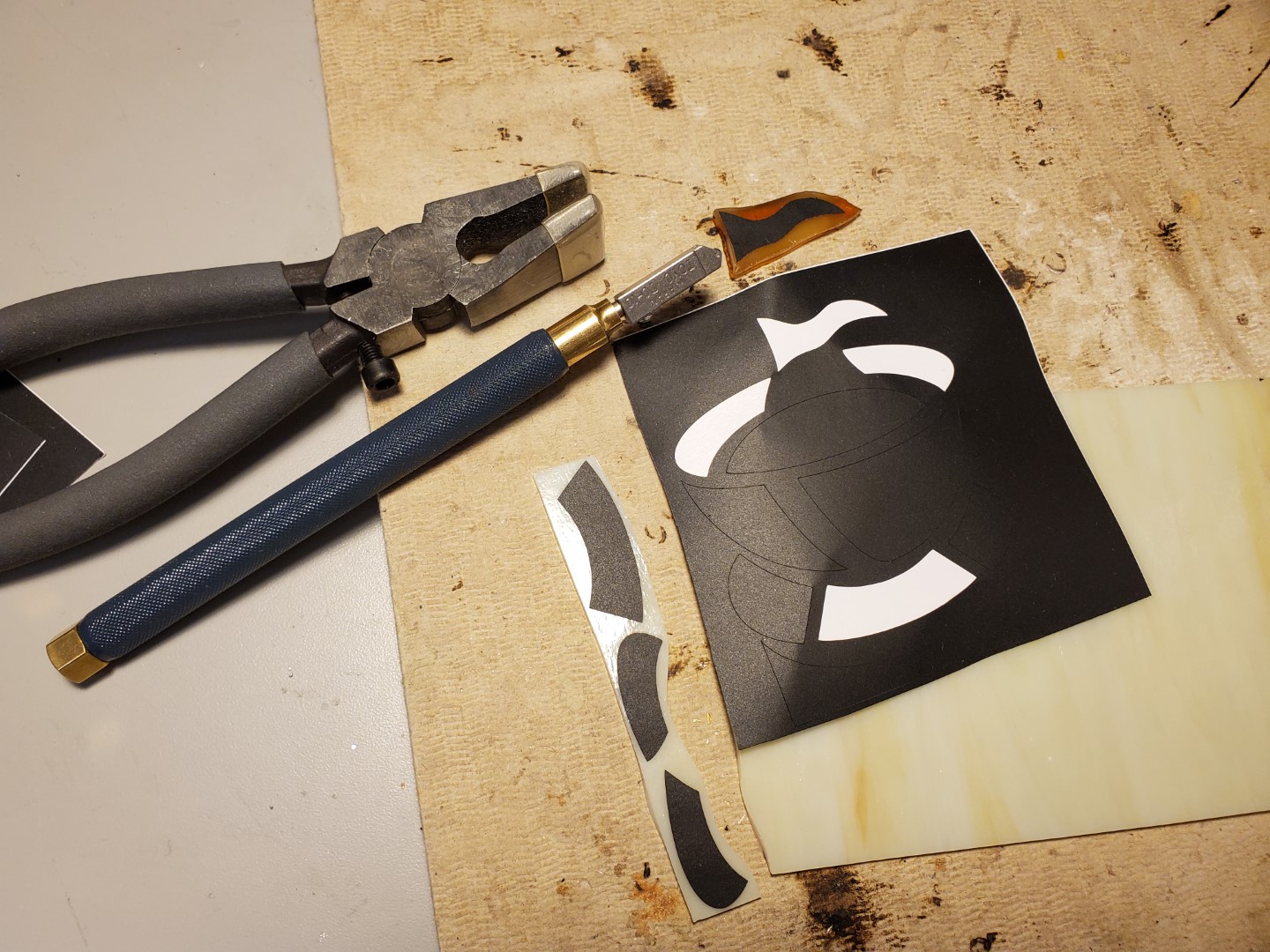
- Cut glass pieces with a glass cutter and specialized pliers, the shape can be rough for now.
- Use a glass grinder to grind each piece down to the exact shape they should be, and then check if they fit. Grind some more if you have to. Remember to leave a gap for the next step.
- Apply copper foil tape to all the edges.
- Using a soldering iron, solder all the glass together by the now-copper edges.
- Clean it. Optionally, apply patina to the solder to give it that dark aged look, and clean again.
- Those chain rings I made, they don’t take on patina very well unless you coat them in solder first. If you don’t, the tin will look black but flake off extremely easily. The soldering process makes a stronger bond with the copper inside the wire.
- The patina will be insulating, to get the circuit working, I rubbed each chain link against each other to get them conductive again.
- If you apply patina, you can still solder under it, it’s just difficult and require flux. For this job I used rosin flux for electronics instead of glass flux.
- It’s a good idea to do at least two passes with the soldering iron, any missed areas won’t react with the patina and will look like copper instead of black. Solder could be covering but not really soldered to some patches of copper, so it’s a good idea to just flux everything up a second time and do a second pass.
The fine folks at Cradle of the Sun (if you live in the SF Bay Area, this could be your local glass shop! map link) have asked me to show them how I make my magic happen:
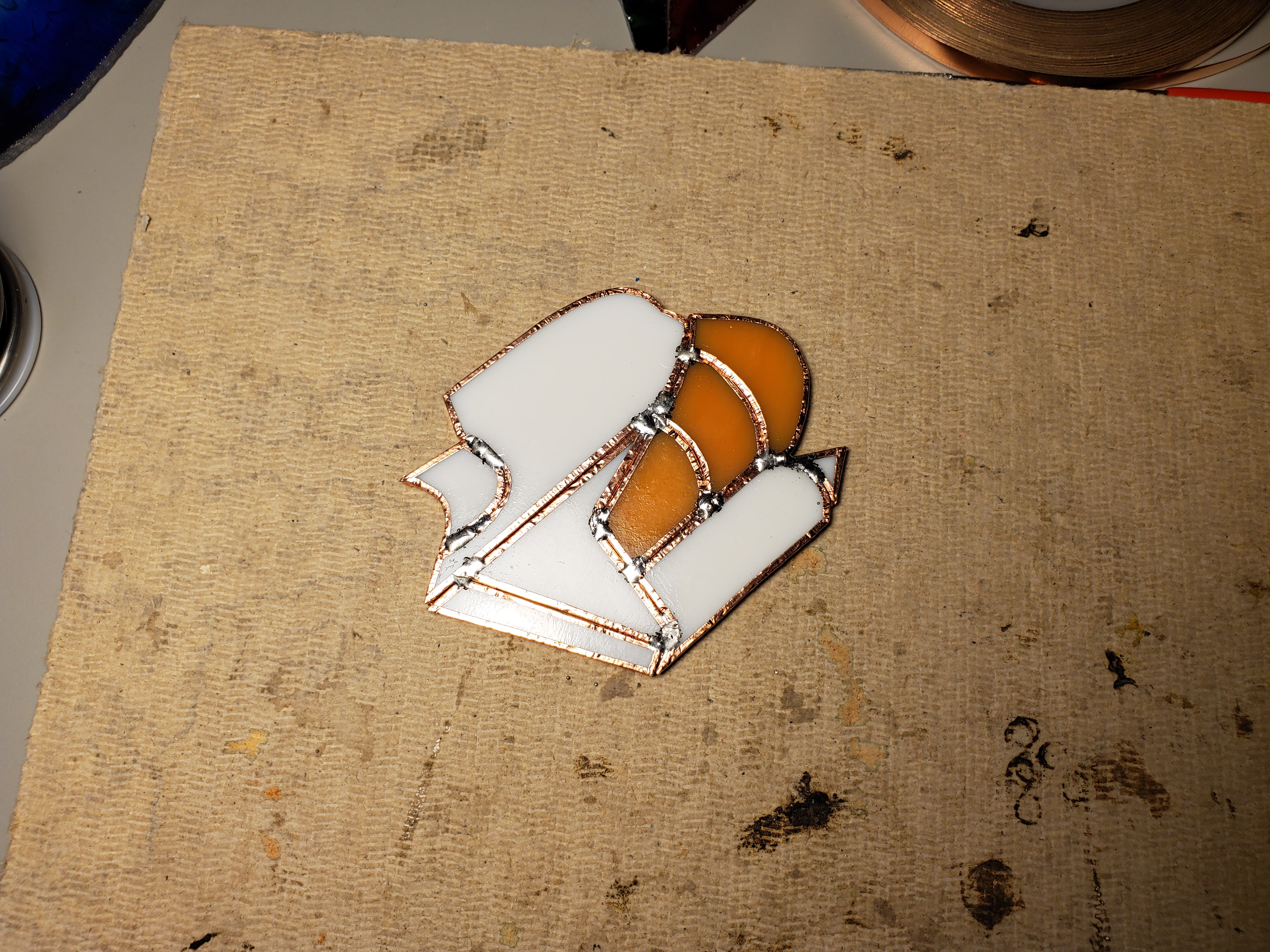
I’ll start by showing you two pictures of the head and tail of the cat with the copper foil attached, look very closely…
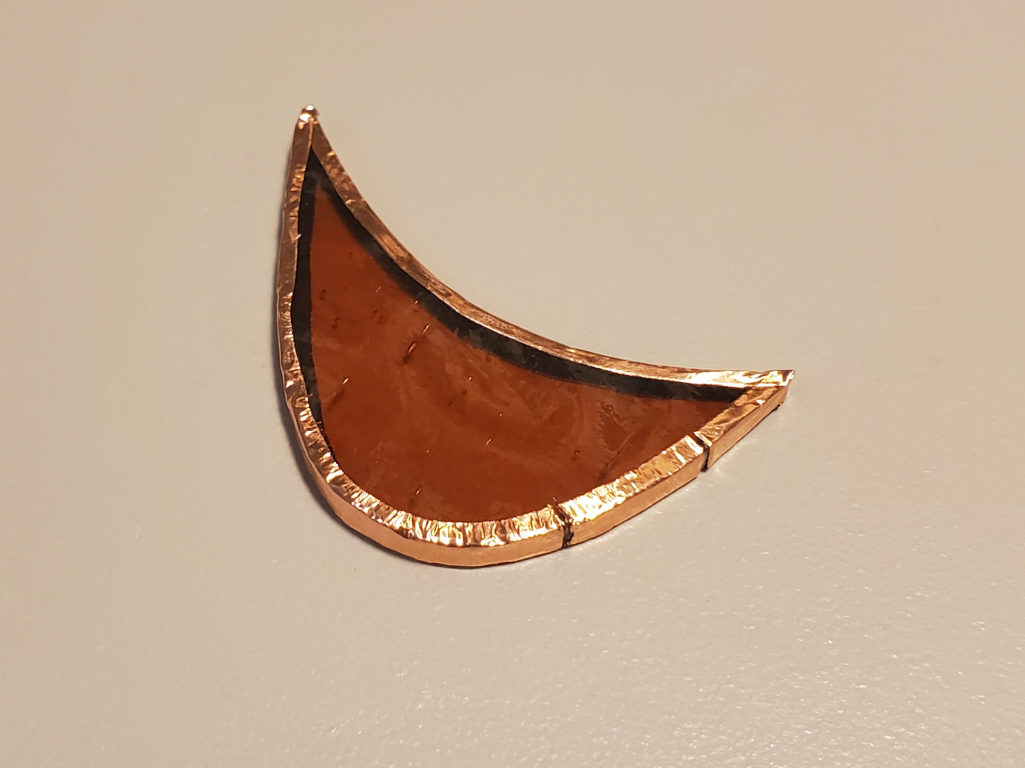
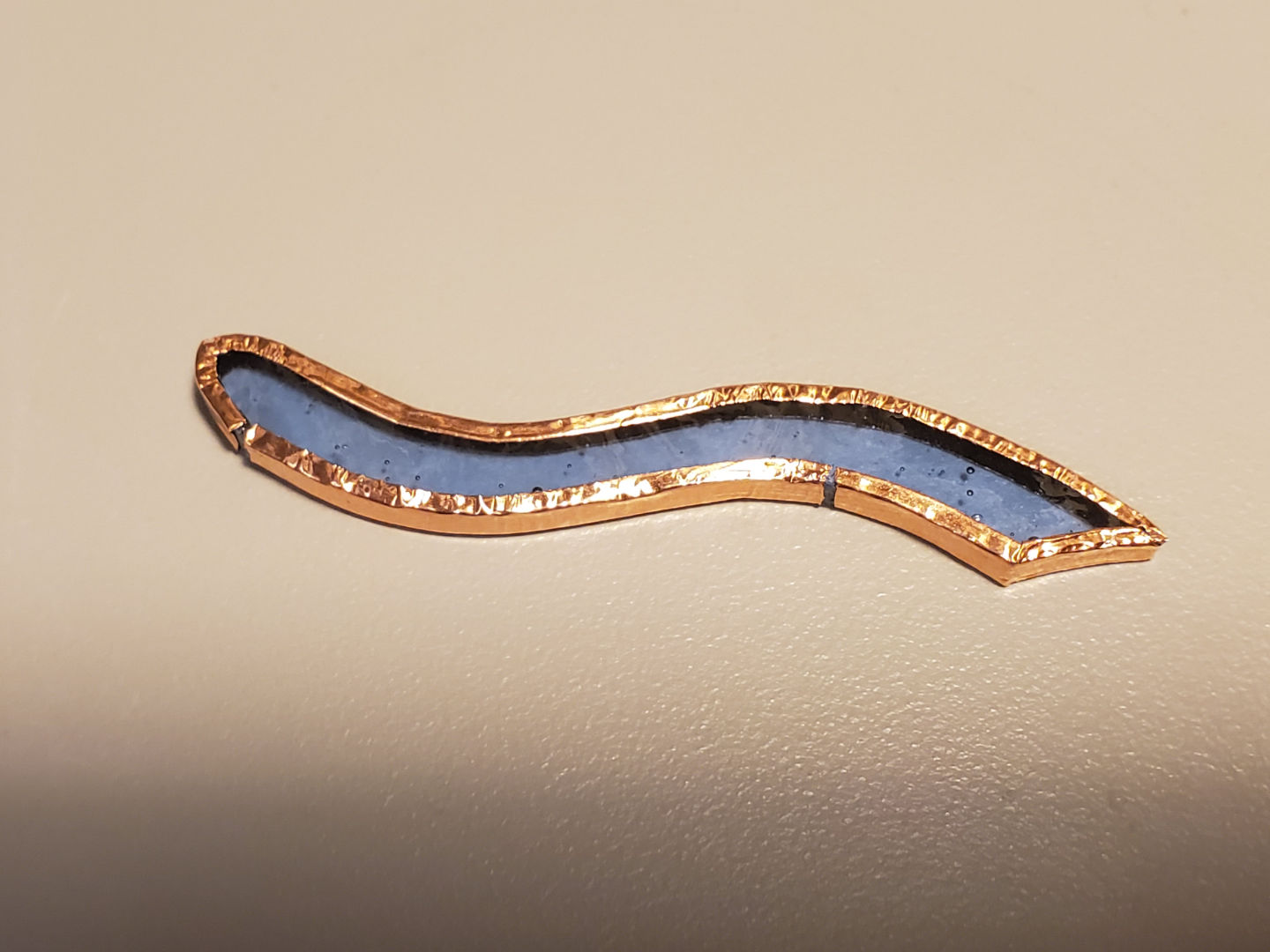
Do you see the gaps in the tape? on each piece, there’s a small isolated portion of copper. Keep this in mind as you read on.
The LEDs is a part of an electrical circuit. This is the most basic circuit, it involves a battery and LEDs in parallel. What’s important is that this circuit has a positive and negative side, electricity will flow from (don’t kill me for saying the next part) the positive side of the battery, through the LEDs, and into the negative side. The gaps in the copper tape is what divides the positive side from the negative side.
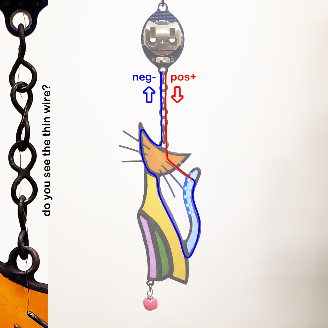
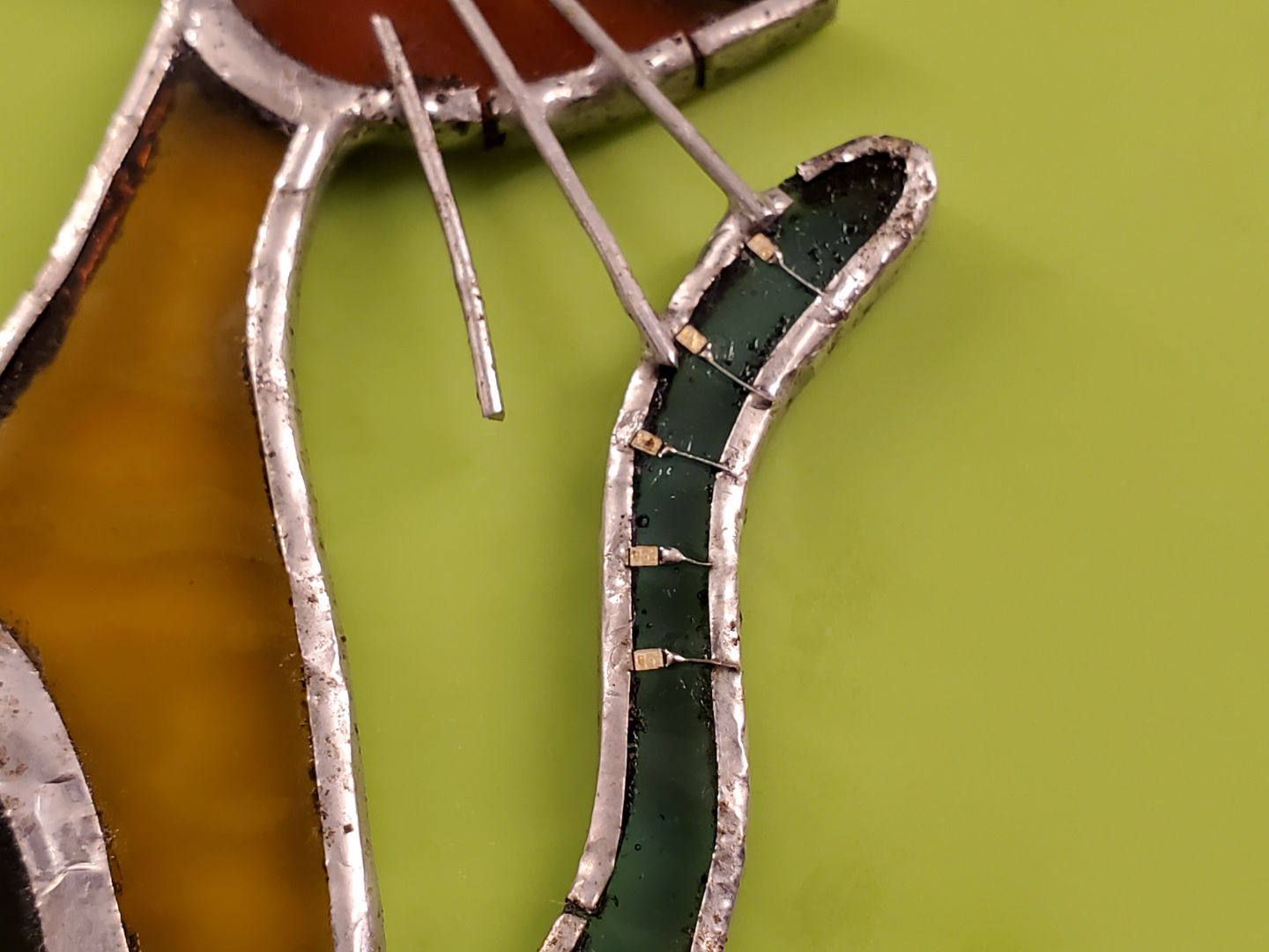
The picture above is showing how the LEDs are soldered onto the tail. The positive/cathode side of the LEDs are soldered to the isolated copper part of the tail, and the negative/anode side of the LED is connected to the outer side of the tail via 30 gauge wiring. The size of the LEDs are tiny, it’s a surface mounted 0603 size, this means no legs.
The isolated/positive part of the tail is connected to the isolated copper part of the head via those cat whiskers. Those whiskers serve as wires. They are also make sure the isolated sections of copper foil do not detach from the glass, the adhesive backing they have is actually fairly weak.
How are the whiskers connected to the battery’s positive terminal? Errr… so I used the thinnest enamel (meaning, insulated) coated copper wire I could buy… so I don’t blame you for not seeing it. It travels up the chain. The chain itself is the negative of the circuit, it links directly to the majority of the copper in the suncatcher.
Up above is a PCB (printed circuit board) I designed specifically for electronic suncatcher projects:
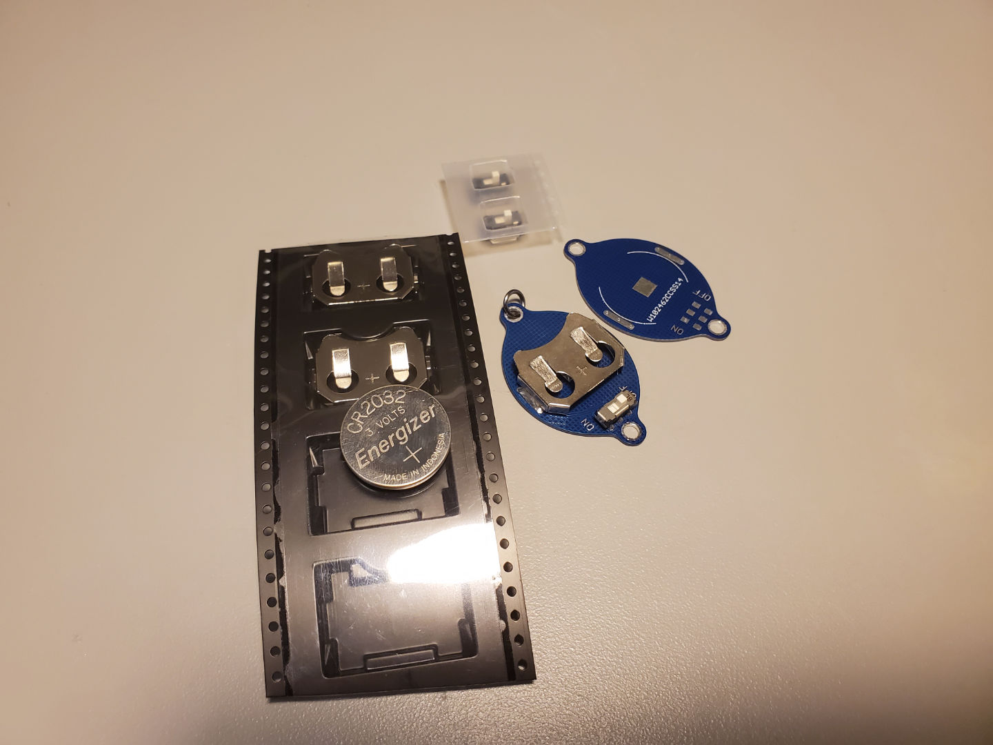
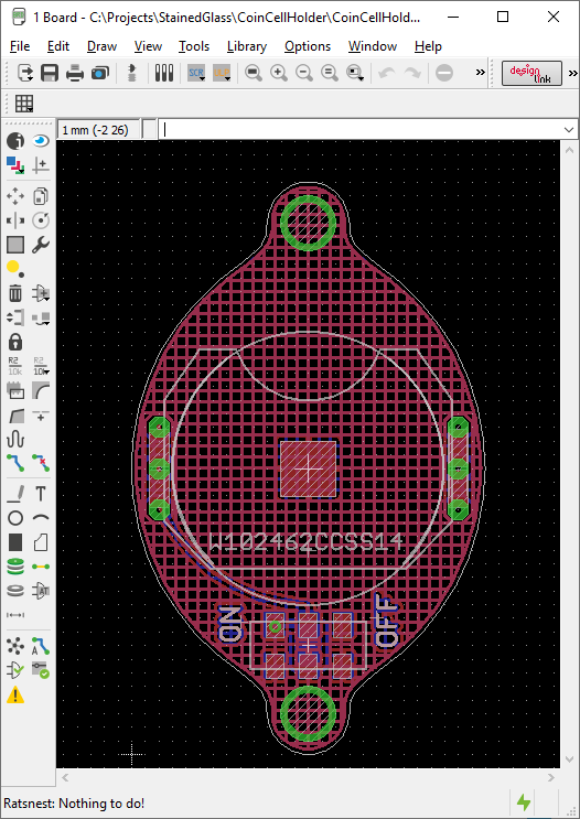
This is a simple small PCB that has only one coin-cell holder and one power switch. The hole is for the chain and is electrically negative. There’s a small hidden solder pad on the back for the positive terminal (sorry the pictures don’t show this). The copper flood is a hatch pattern to give it some interesting texture easily.
A lot of larger stained glass artwork are hung by two chains instead of just one, so one chain could be positive and another chain could be negative.
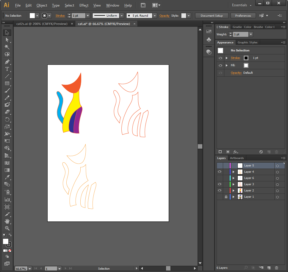
If anybody is wondering, everything is created through Adobe Illustrator first, then cut out onto waterproof vinly stickers sheets with a die cutter.
The rings are created with 18 AWG wiring, which is copper but tin plated.
Applying black patina for the first time in my life… I’ve learned a few things:
On to something bigger…
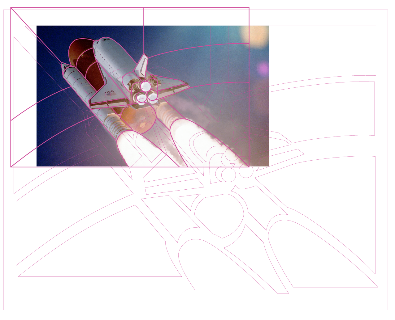
Stained Glass Space Shuttle
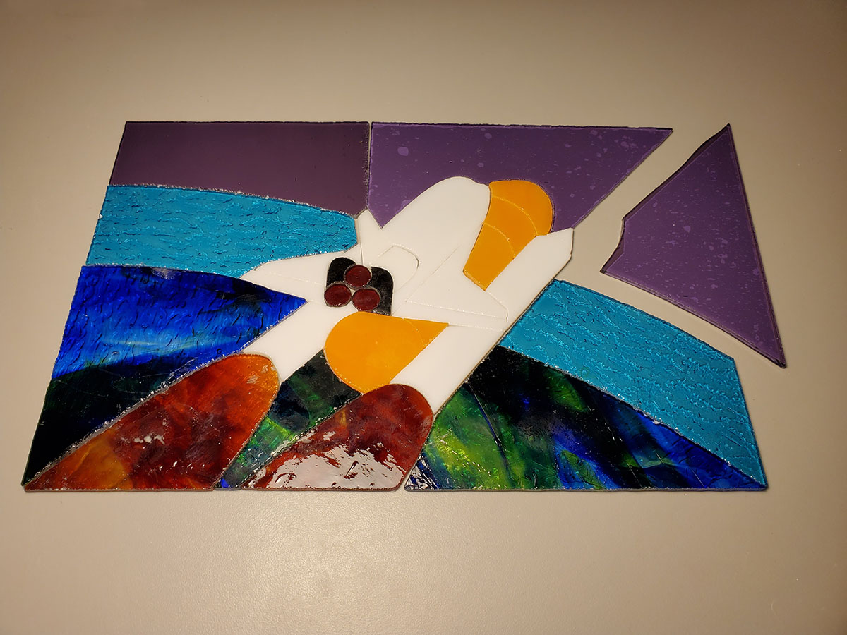
Again, using Illustrator. When I am happy with the design, I make the lines about 0.8mm thick to account for the thickness of the copper foil tape, then I use “outline stroke” before spacing out each piece for die cutting.
The previous cat suncatcher had many curves that are forgiving because there’s no mating adjacent piece. This space shuttle panel is different, everything had to fit perfectly. Do not foil up all the glass pieces all in one go. Instead, start assembly from the middle outwards, and start with a piece that’s the most difficult to re-grind. Do it piece by piece so that you can make adjustments.
I used copper U-channels on the outer perimeter to give the whole project more structural integrity. Glass is quite heavy, the adhesive on the back of the foil isn’t great, and solder is soft, so if you want to make a large panel stiff, use something solid to frame it. At some point, project will become so heavy that it’s necessary to use lead/zinc/copper came everywhere just so it doesn’t fall apart under its own weight.
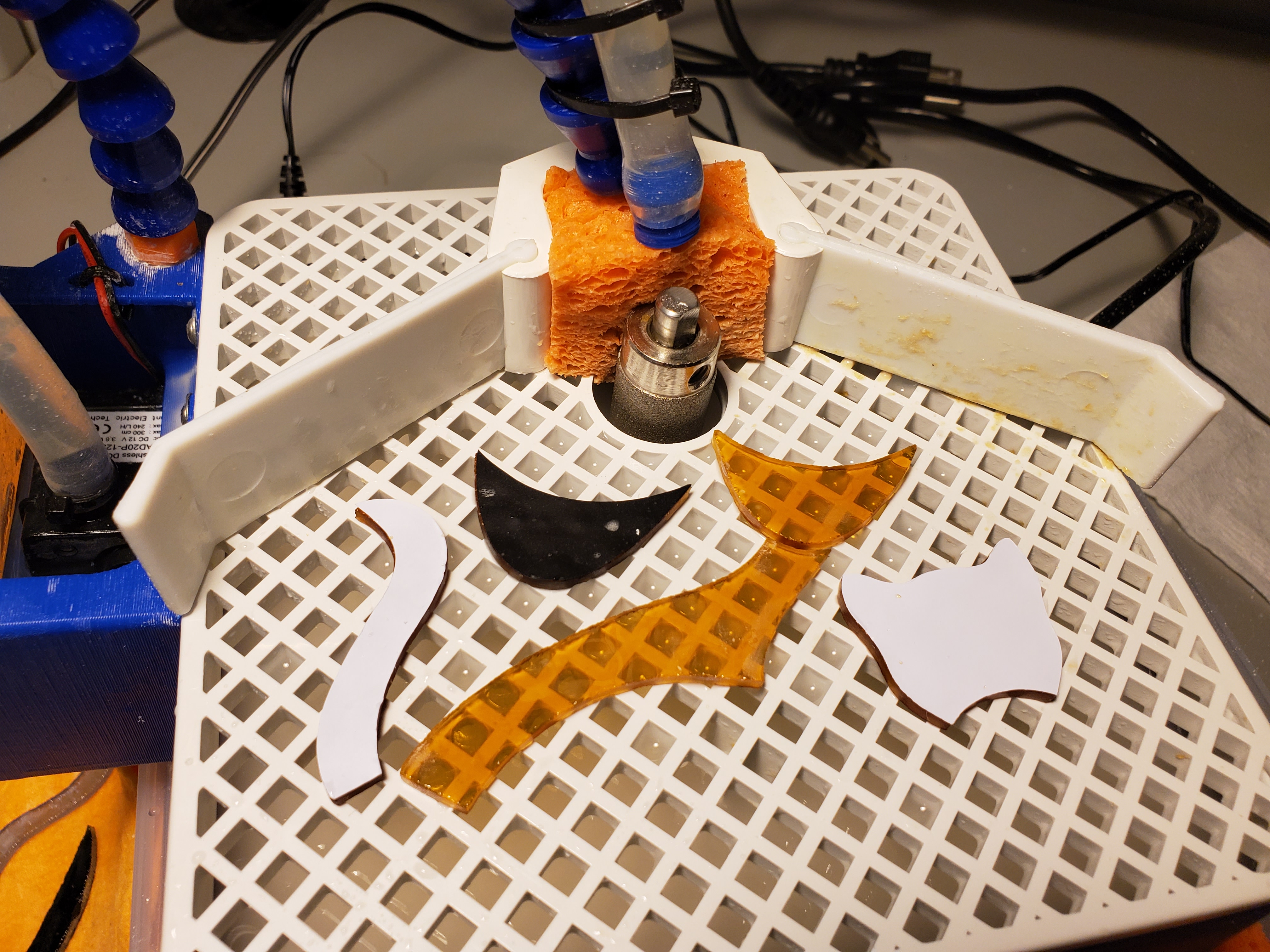
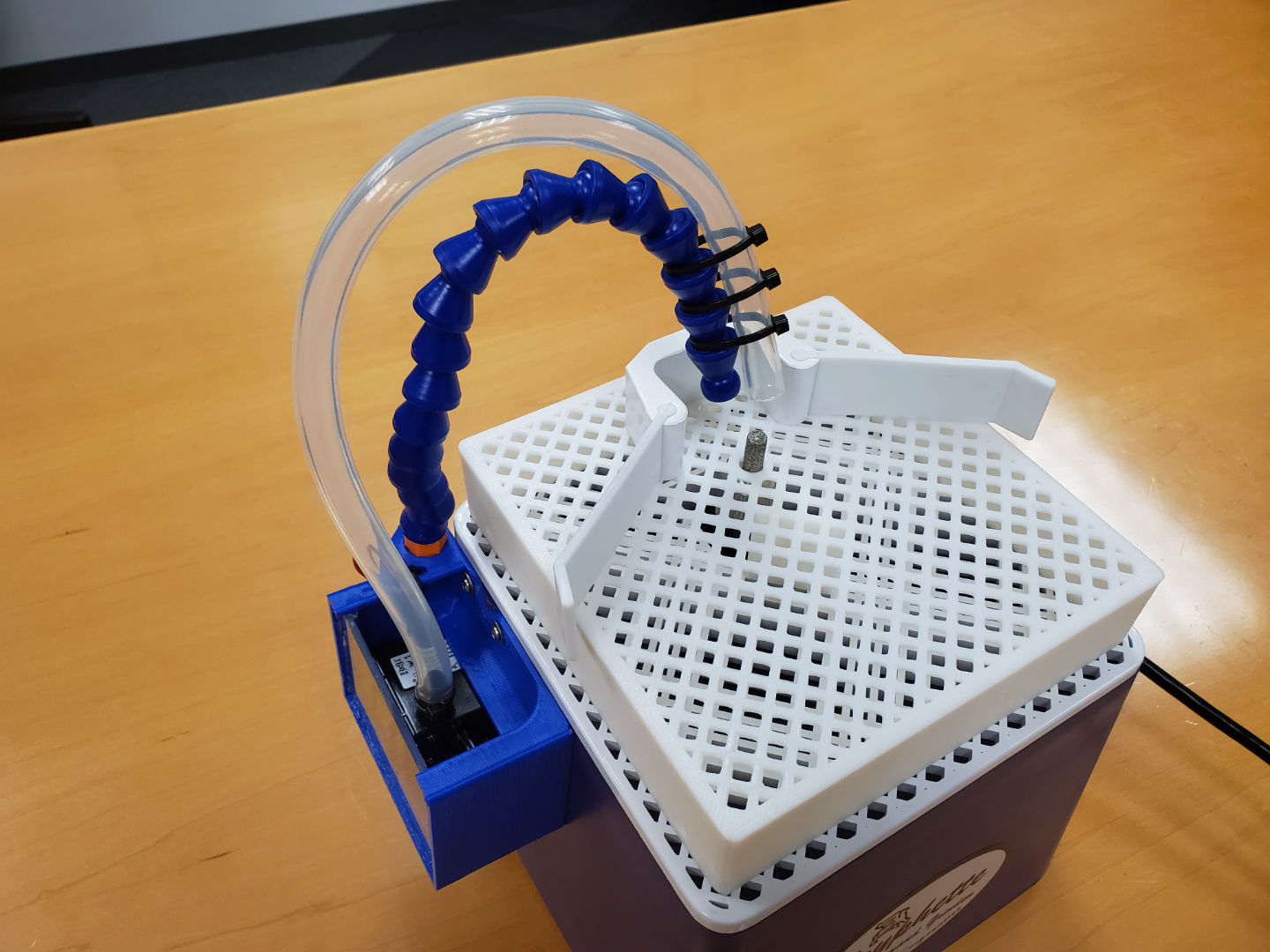
3D Printed Glass Grinder Accessories
I purchased the cheapest glass grinder I could buy, but I got every sized and grit of grinder bits I could buy. A smaller bit would let me grind tighter corners (I check if a corner needs a smaller bit while I design in Illustrator). Due to the way the bits attach to the grinder shaft, you need to get a riser, which would cost about $20 (and they don’t even make one for my model of grinder).
It’s just plastic… so I 3D printed one.
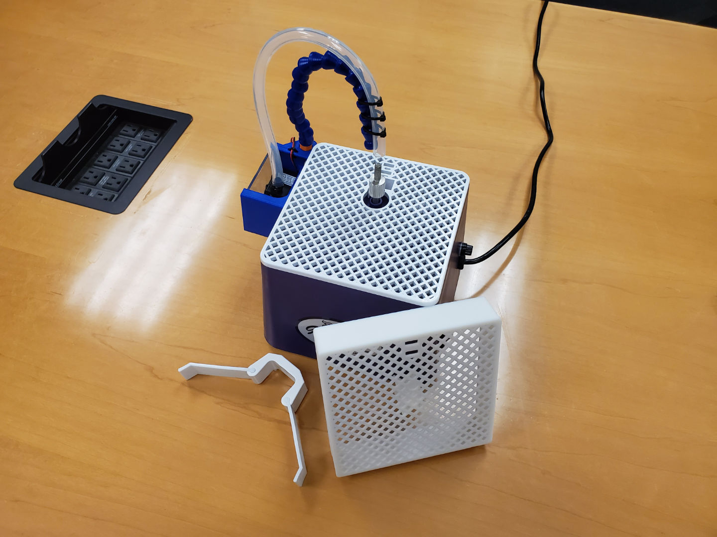
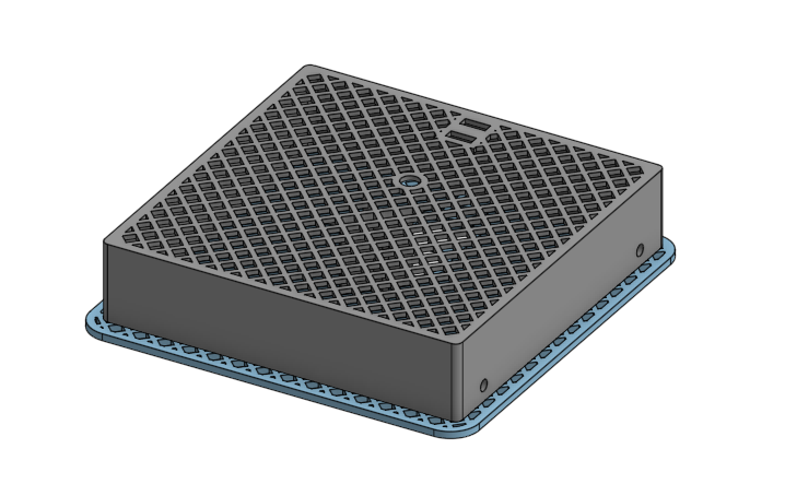
If you are looking for the CAD model files, please visit this link.
What’s the blue arm and the tube? Well… I also designed an entire water pumping system on my own, and it works, but it’s useless because the water spray from the grinding causes the closed-loop system to lose water too fast anyways, and the reservoir I designed isn’t large enough (not pictured is the valve I attached to slow down the water flow). I had to refill it too often, so it’s better to just pour more water into the sponge rather than the reservoir. (also not pictured is the sponge)
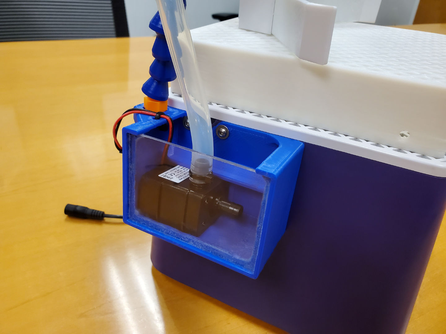
This pump is very versatile, it’s the same pump I use to circulate the oil around my aquarium computer.
Something Quick
This piece took only one day.

It was gifted to my favorite breakfast joint, proudly on display right in front of “my seat” there.

Hmm… should’ve made it bigger. It was designed to hang.

Awesome, thanks for sharing that – very inspiring!
Could one use a black, milled PCB for the LED traces?
Could one use a 3D resin printer for making the main frame?
Laser-cut colored translucent acrylic pieces?
Resin printed plastic deforms pretty quick under any sort of stress. For small pieces it might work.
Acrylic probably can’t handle the massive amount of heat that the copper foil method needs. It can probably handle it if you use zinc or lead came instead.
I want to play with incorporating PCBs too but I need it to look good, I don’t have a good idea yet and I’m not rushing it, not sure what would work well.