
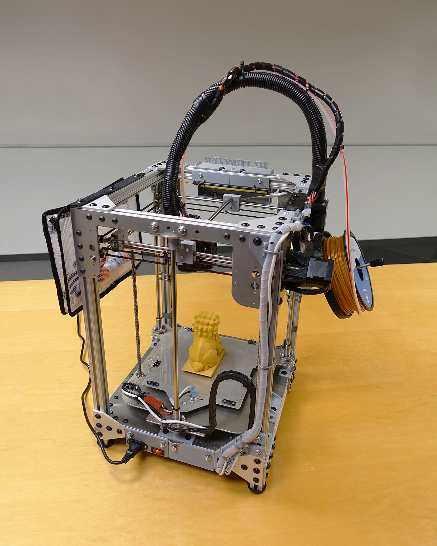
I finally did it, I designed and built my own 3D printer. This is in no way “the best 3D printer”. Instead, this was an epic and nightmare project that exercised my ability to engineer and build my own CNC machine. Along the way, I figured out what I did well and what I did badly, mistakes were made and sometimes fixed, even ignored.
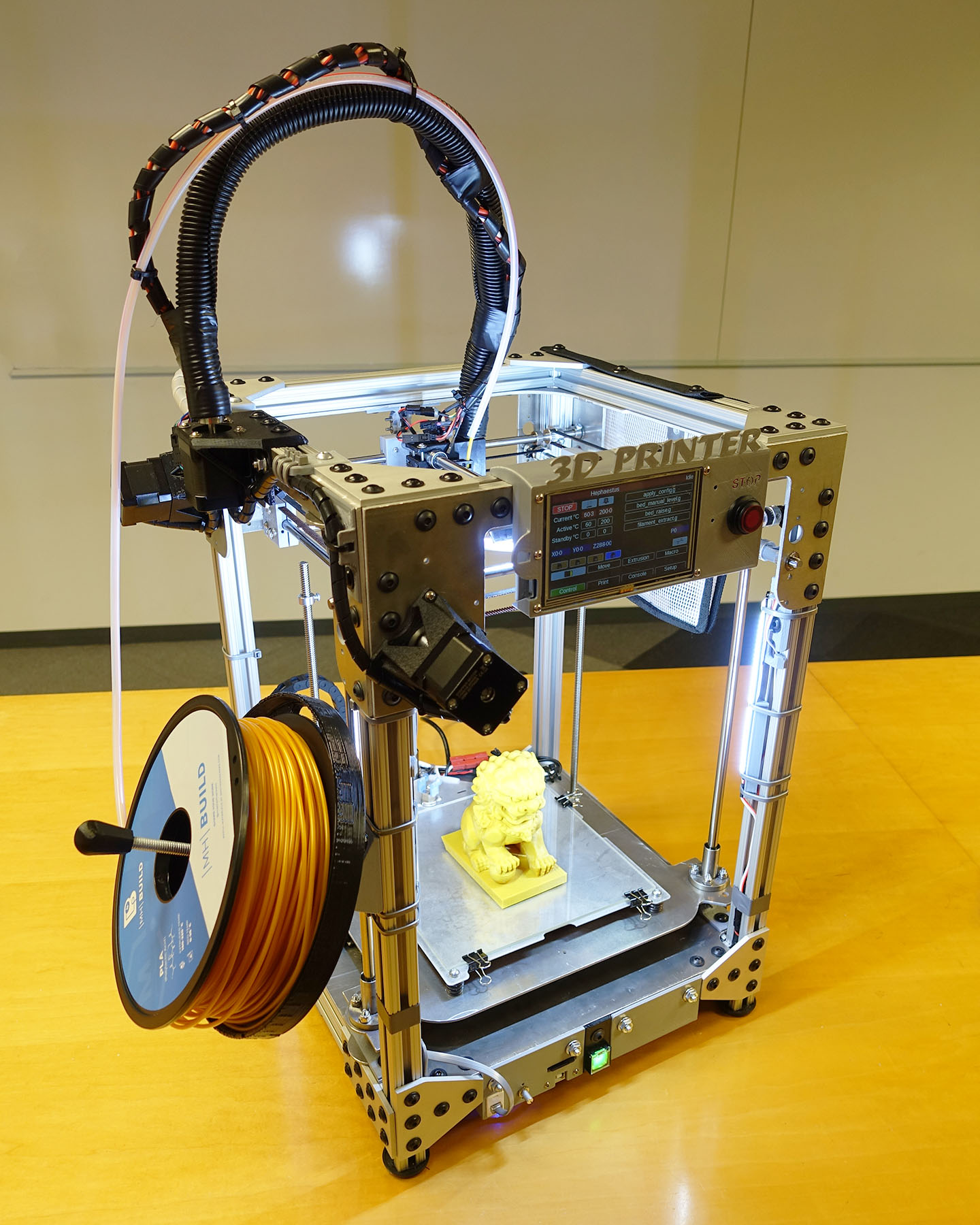
This 3D printer is named Haphaestus. This wasn’t some kit that I purchased and put together, this wasn’t some tutorial I downloaded and followed. I designed almost everything about this printer and built it with tools I own and a waterjet cutting service. The only application specific parts I didn’t design are the Duet controller circuit and the E3D Titan parts.
NOTE: This is not an open source project where I will let you download a few files so you can build one yourself, trust me… you don’t want to. It’ll be a logistical nightmare to just organize the files and BOM to the point where it is useful to anybody else.
This page will be dedicated to recording my experiences and analysis of the first 3D printer I have ever designed and built all by myself.
More pictures of prints near the bottom of this page!
Features and Performance
- Print size: about 190mm x 170mm, borosilicate glass. Build height: 288 mm
- 24V electrical system, 200W silicone heated bed, 65W hotend heater
- Custom extruder that is flexible shaft driven and worm gear reduced. Uses Bondtech geared hobbed wheels
- All metal hotend, E3D heatsink (aluminum) + heatbreak (steel) + heatblock (copper). 3D Solex nozzles (Matchless Race). PT100 sensor
- Duet WiFi control circuit running a flavor of RepRapFirmware. 32 bit microcontroller and Trinamic stepper motor drivers. PanelDue 5i used for control panel with easily accessible USB port and SD card slot
- Printhead moves in Cartesian X-Y by belts (Gates® PowerGrip™ brand, two belts per axis). Bed moves up and down in Z axis with two leadscrews
- 3 point bed leveling without sensors, ultra stiff springs for stability and large knobs for easy adjustments
- Adjustable constant voltage (flicker-free) LED lighting system
- All silicone insulated power wiring
- Custom MOSFET heater circuit rated for 200A bursts, opto-isolated from main control circuit, protected by an army of flyback, TVS, and Zener diodes
- Uses shielded cabling with unused signals for future add-on accessories
Theoretical Print Resolution
- X and Y is 80 steps per mm, that’s 0.0125mm resolution
- 20 teeth pulley, 2mm pitch belt, 200 steps per rev stepper motor, 16x microstepping
- Z axis is 0.04mm resolution
- TR8X8 leadscrew, 200 steps per rev stepper motor, 1x microstepping
I don’t have measurement tools that I can use to make real tolerance claims. I’m using mostly the same pulley and motors as all other printers. I am using higher quality components, a more rigid frame, and cutting edge electronics, so it should be as good or better than my Ultimaker 2 in terms of print capability. Please see the pictures of the test prints for qualitative results.
Quantitative Heating Results
Normal warm up (200C nozzle, 60C bed) before a print takes 1 minute 30 seconds. It took 2 minutes to get up to 90C bed temperature, honestly I’m kind of scared to push it to the limit
M303 tuning results (for bed heater): gain 222.7, time constant 432.5, dead time 3.1
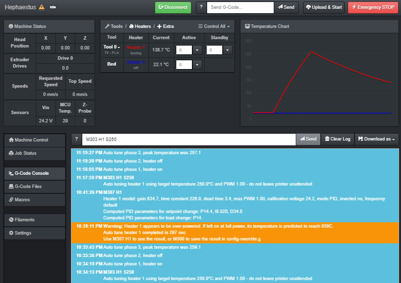
M303 tuning results (for nozzle heater):
All heaters on and all motors on max holding current, the power draw was measured at 340 watts.
Print Quality
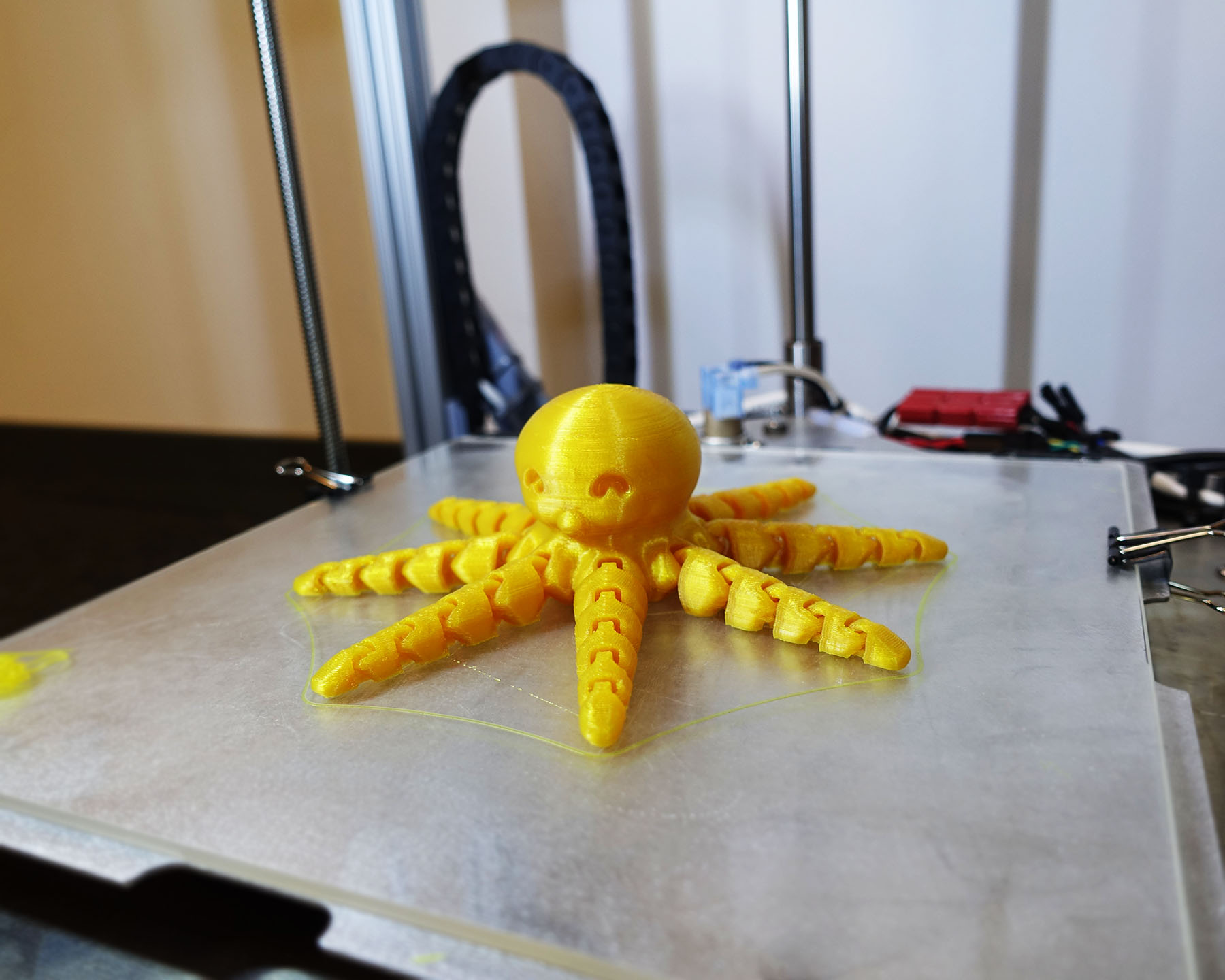
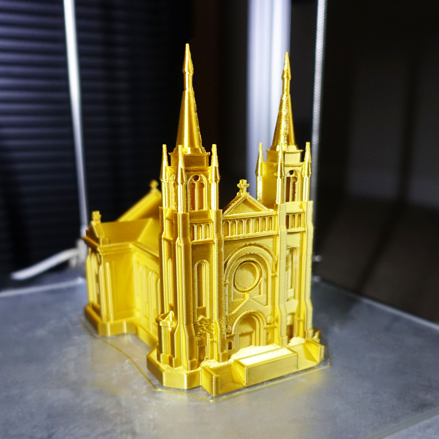
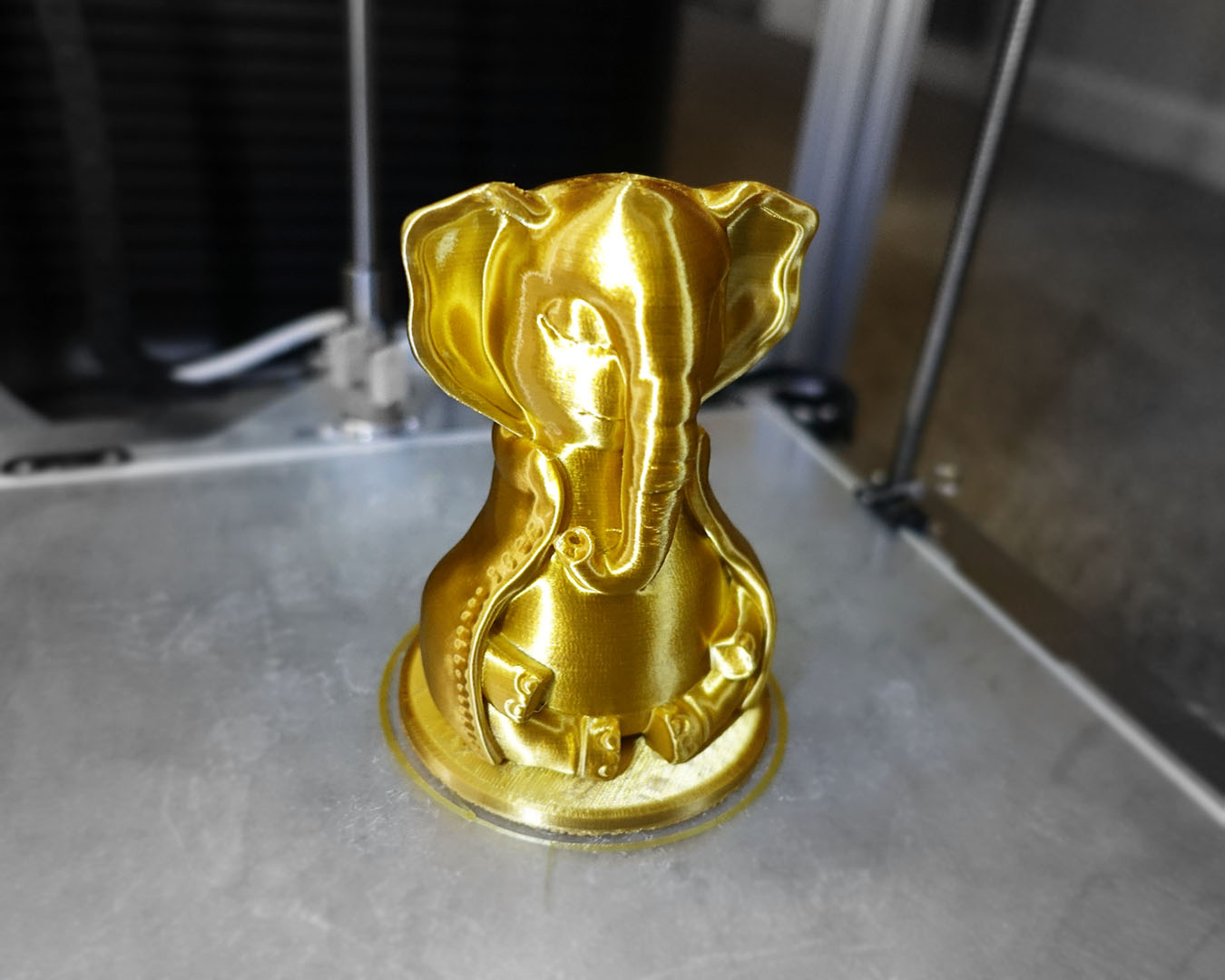
Maiden Print
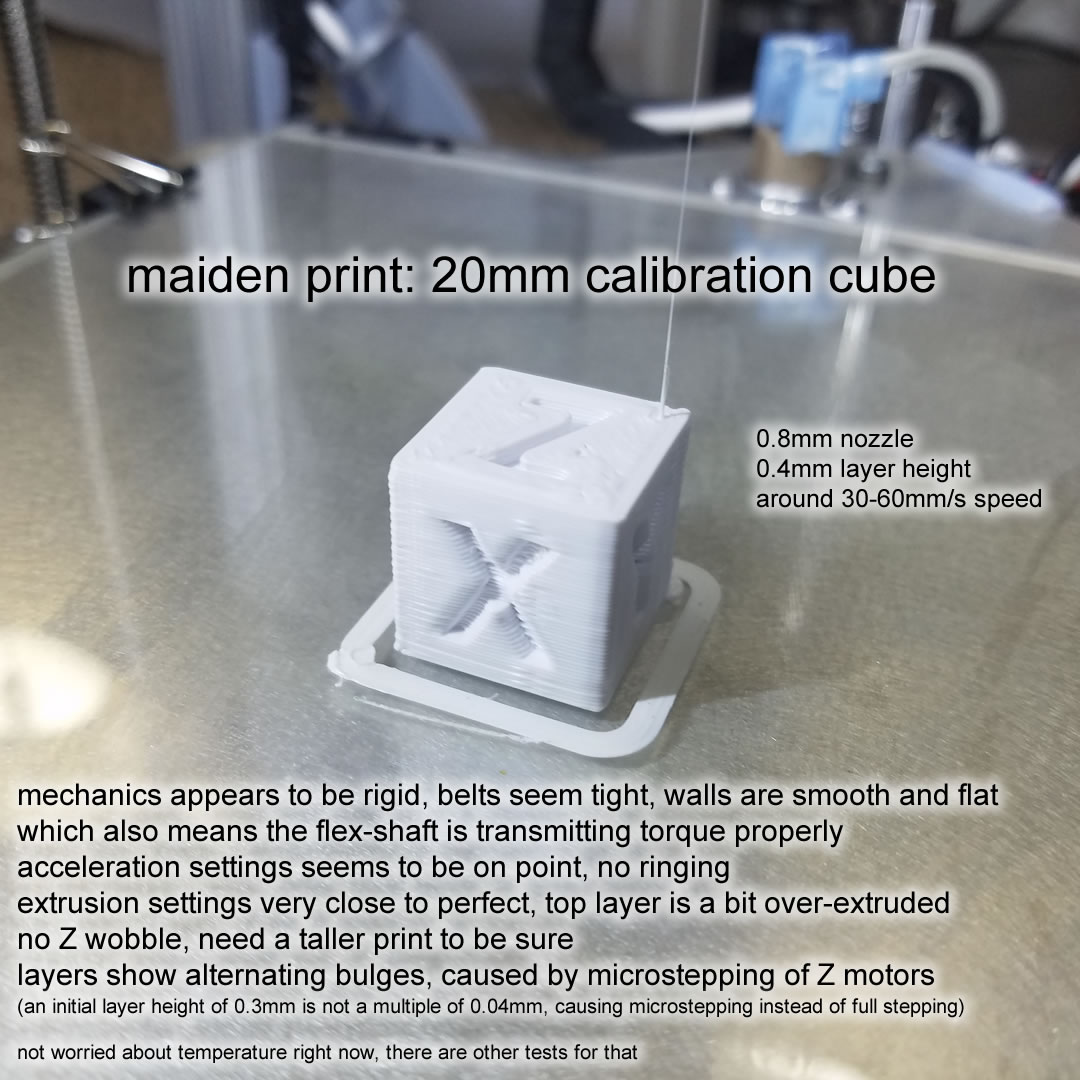
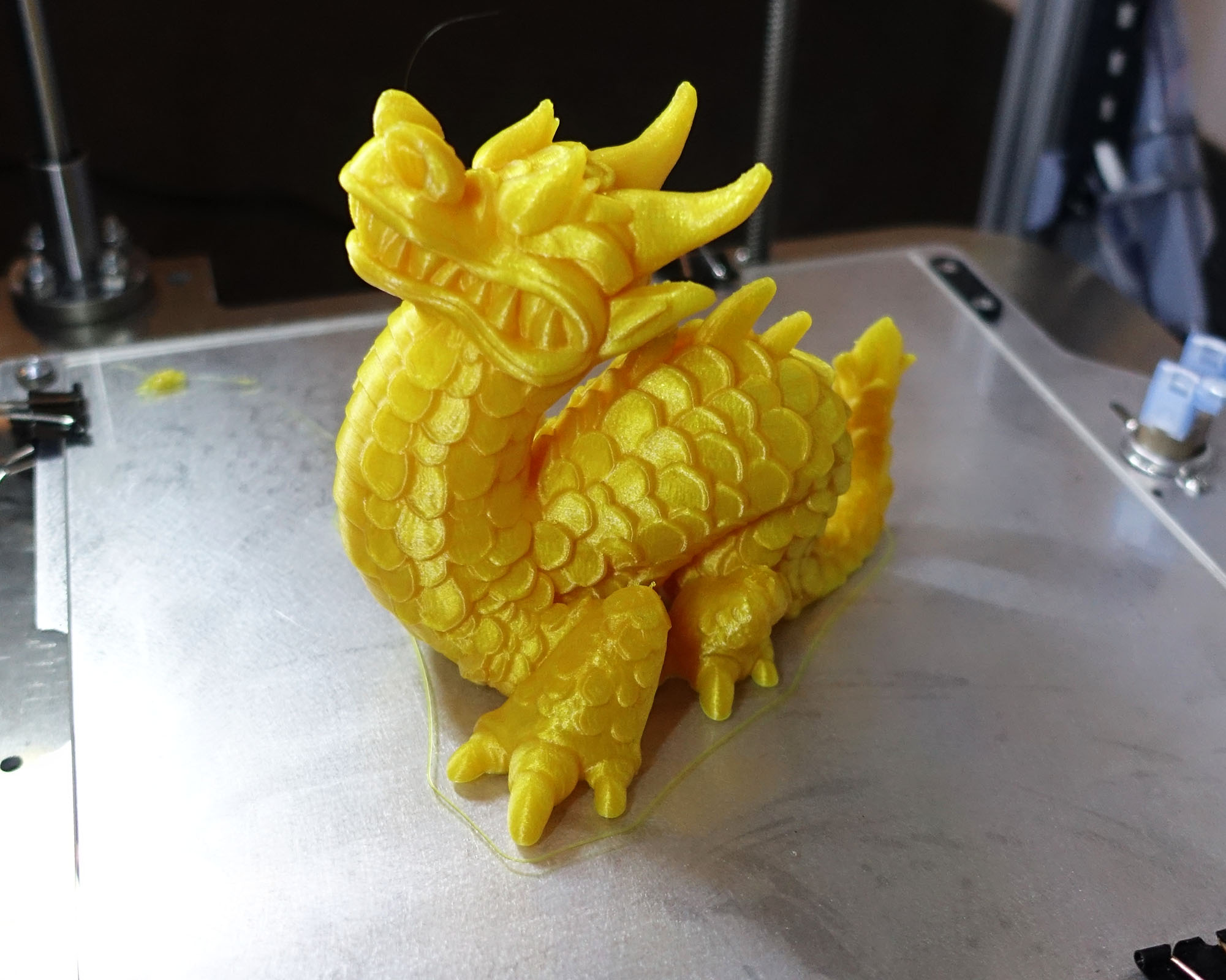
It is very satisfying to get a nearly perfect maiden print off of a printer you personally designed and built. This print proves that the physical design and construction of the printer is sound, everything else can be fixed with configuration tweaks. The above print was printed with the V1 extruder and 0.8mm nozzle.
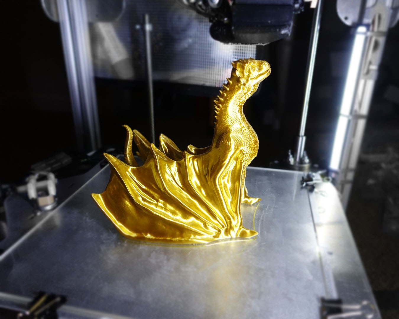
More Test Prints
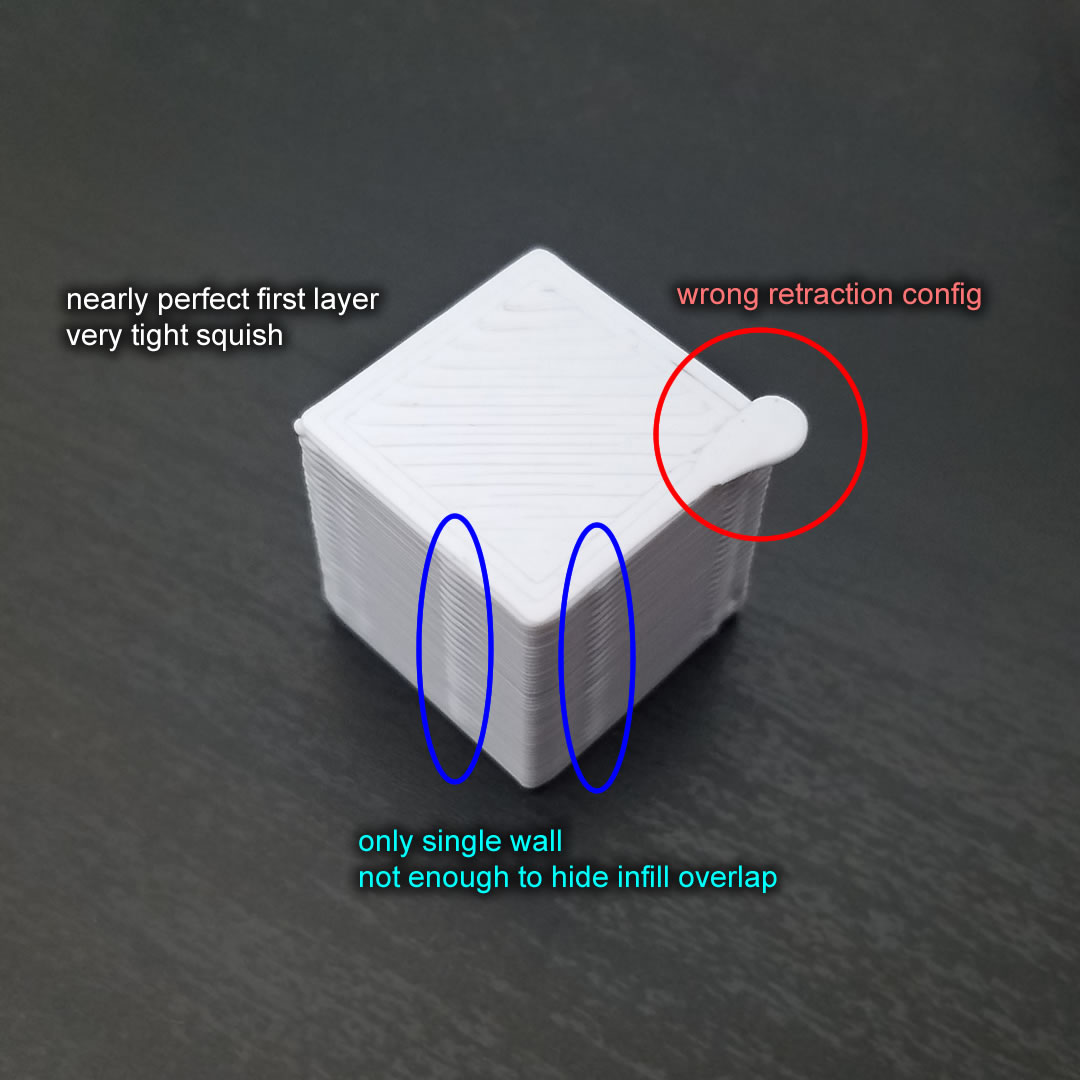
This print was done using the same V1 extruder but at a much more common 0.4mm nozzle setting:
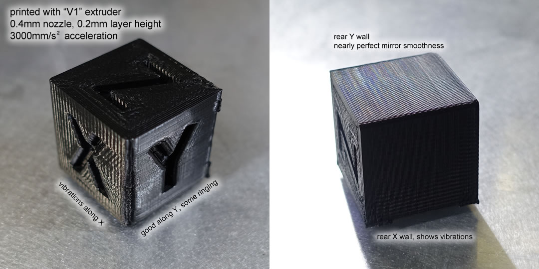
(the lighting of the photo was chosen and the filters were applied to clearly highlight the problem, it doesn’t look nearly that bad in real life)
After that print, V2 of the extruder was designed and built. The new extruder design had a better center of gravity placement, and better linear bearing placement, to avoid the vibrations. The acceleration setting was also turned way down to help with the vibrations and ringing.
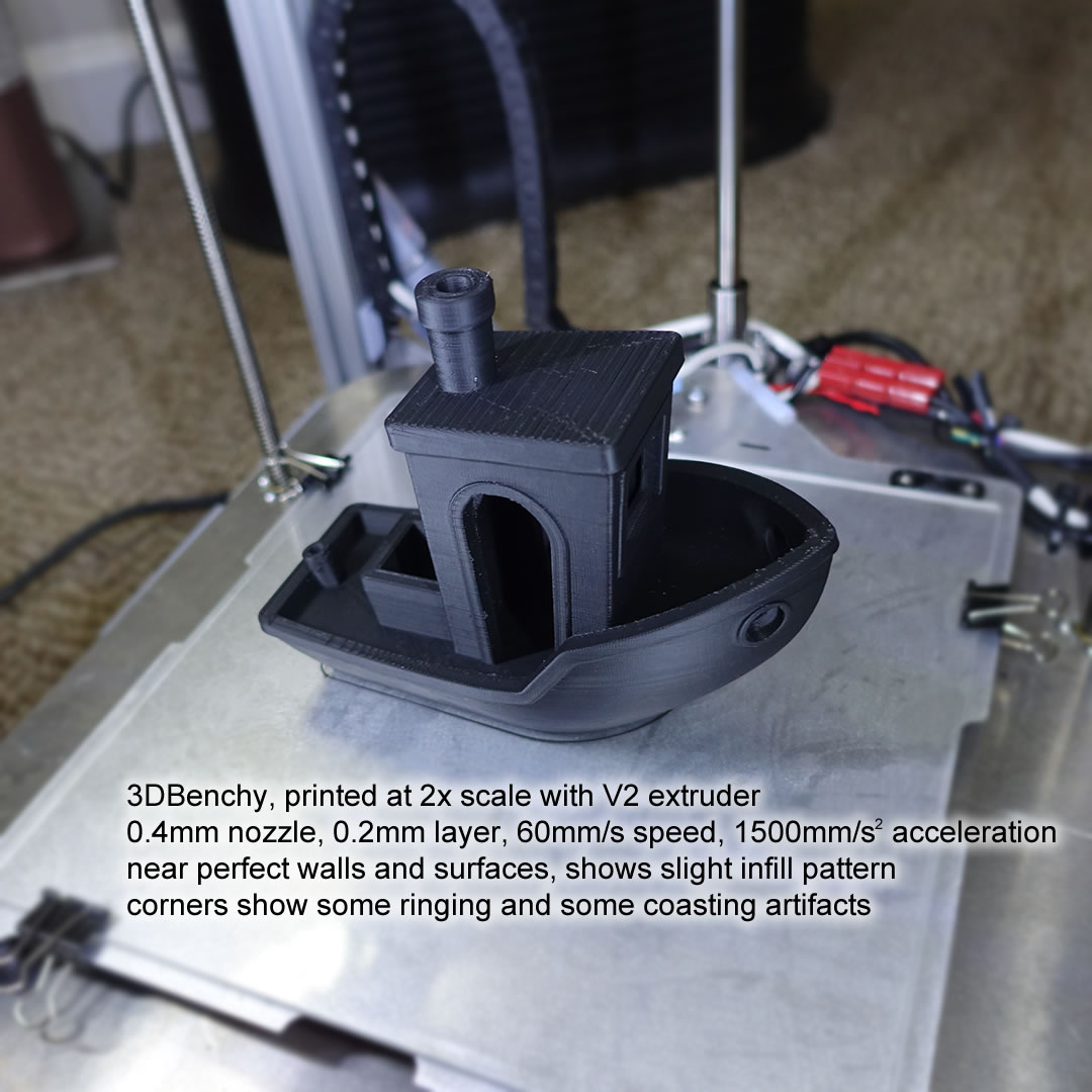
The following picture is a 2x scale Benchy printed with the V2 extruder, 0.4mm nozzle, 0.2mm layer height, 60mm/s speed, and 1500mm/s^2 acceleration instead of 3000:
Here’s a temperature tower test, which shows overhang, bridging, and retraction/stringing performance at various temperatures:
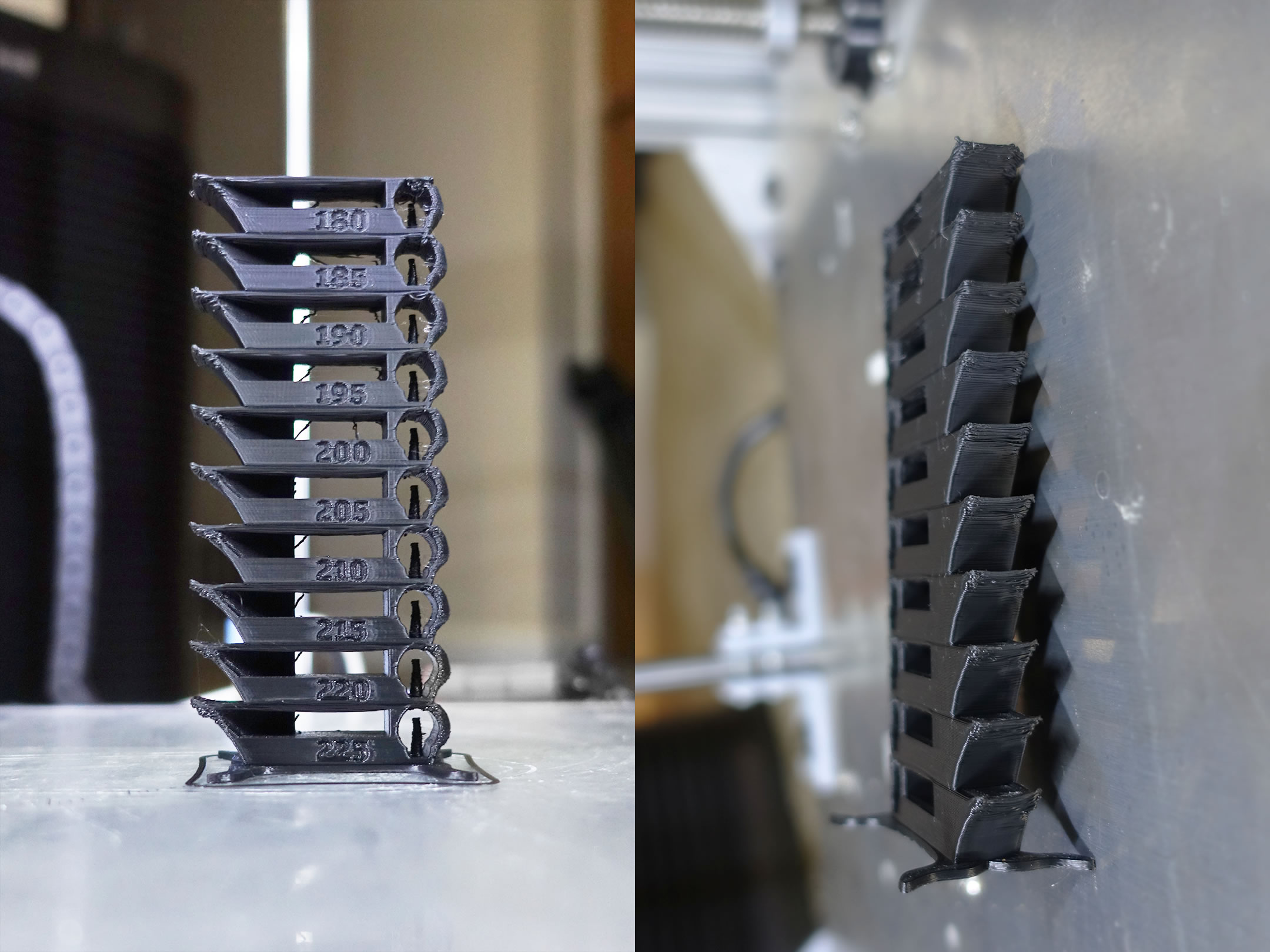
That test was done with default settings, of course speed settings could affect the performance drastically, but the results here does show that I have a very good starting point already.
Here’s a torture test, a lattice cube:
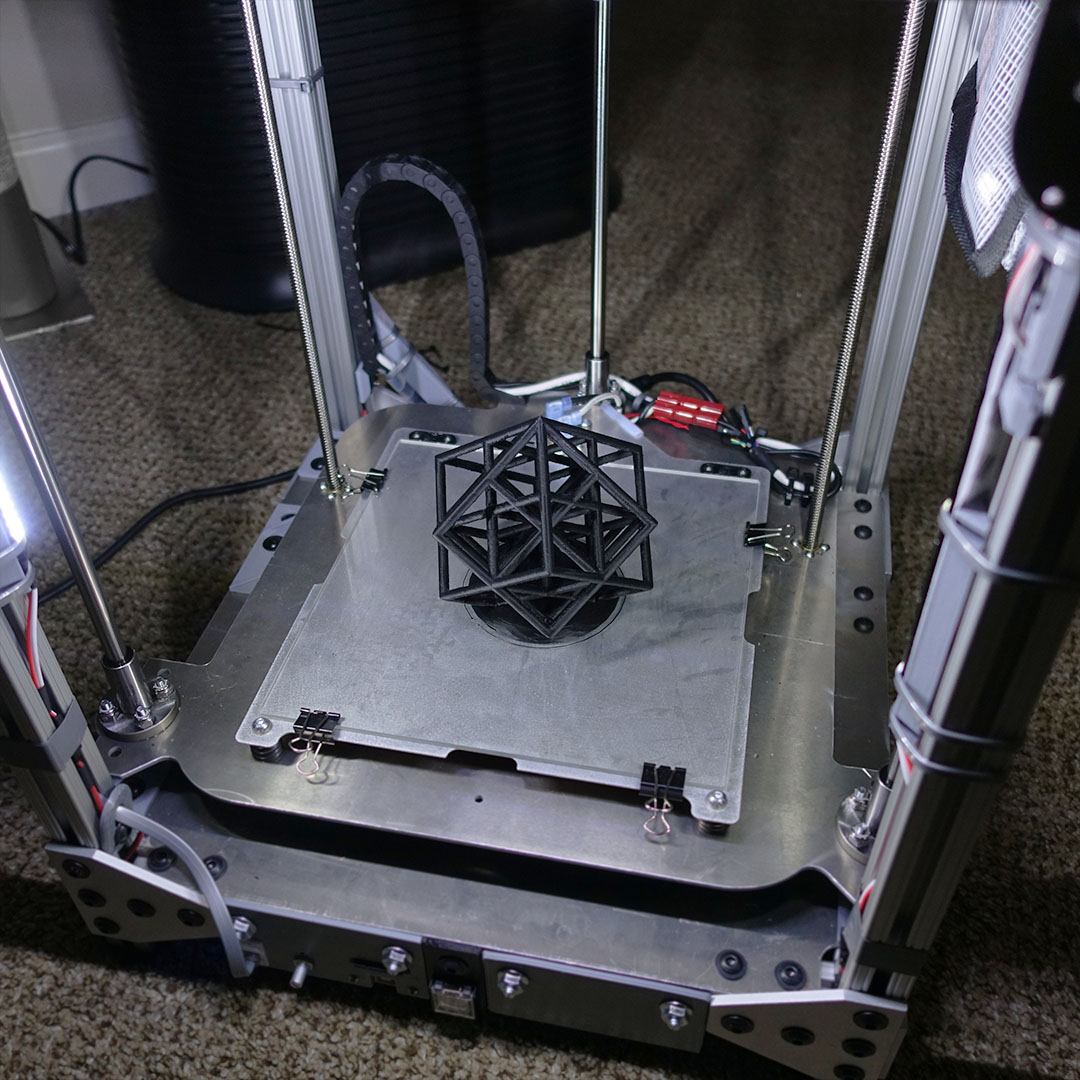
With this object, the printer is forced to print many thin branches, traveling between them sequentially, retracting the filament during the travel moves. The branches are thin and weak and also at an angle, the angle causes the plastic to curl upwards, depending on the heat of the nozzle and the cooling fan. All of this means that the printer has a high chance of breaking a branch either through vibration or simply hitting the branch with the nozzle. This is a good test to see how good the retraction settings are (how many stringing/hairs between branches), if the nozzle is at the right temperature (strong branches with good smooth surfaces at all angles), how effective is the cooling fan (good cooling means less curling, and thus less chance of a branch breaking when being hit), and how stable the printer is (not shaking so much that the branches break, and being able to absorb some of the hits that the branches do inevitably take).
Design and Construction Topics
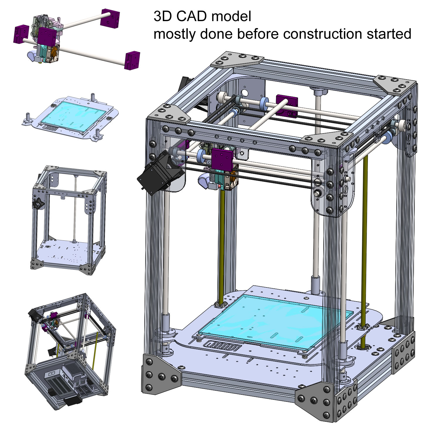
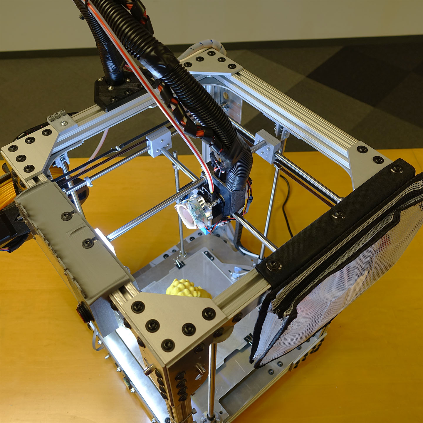
Frame
I definitely wanted a box frame. Other styles are the upside-down-T (think of Prusa and Creality), and cantilever (think of the Printrbot, Monoprice Mini), both are less sturdy than a box frame. Of course, a full box needs more material and is generally heavier (except the Ultimaker, which is an all-plastic box, so it’s quite light).
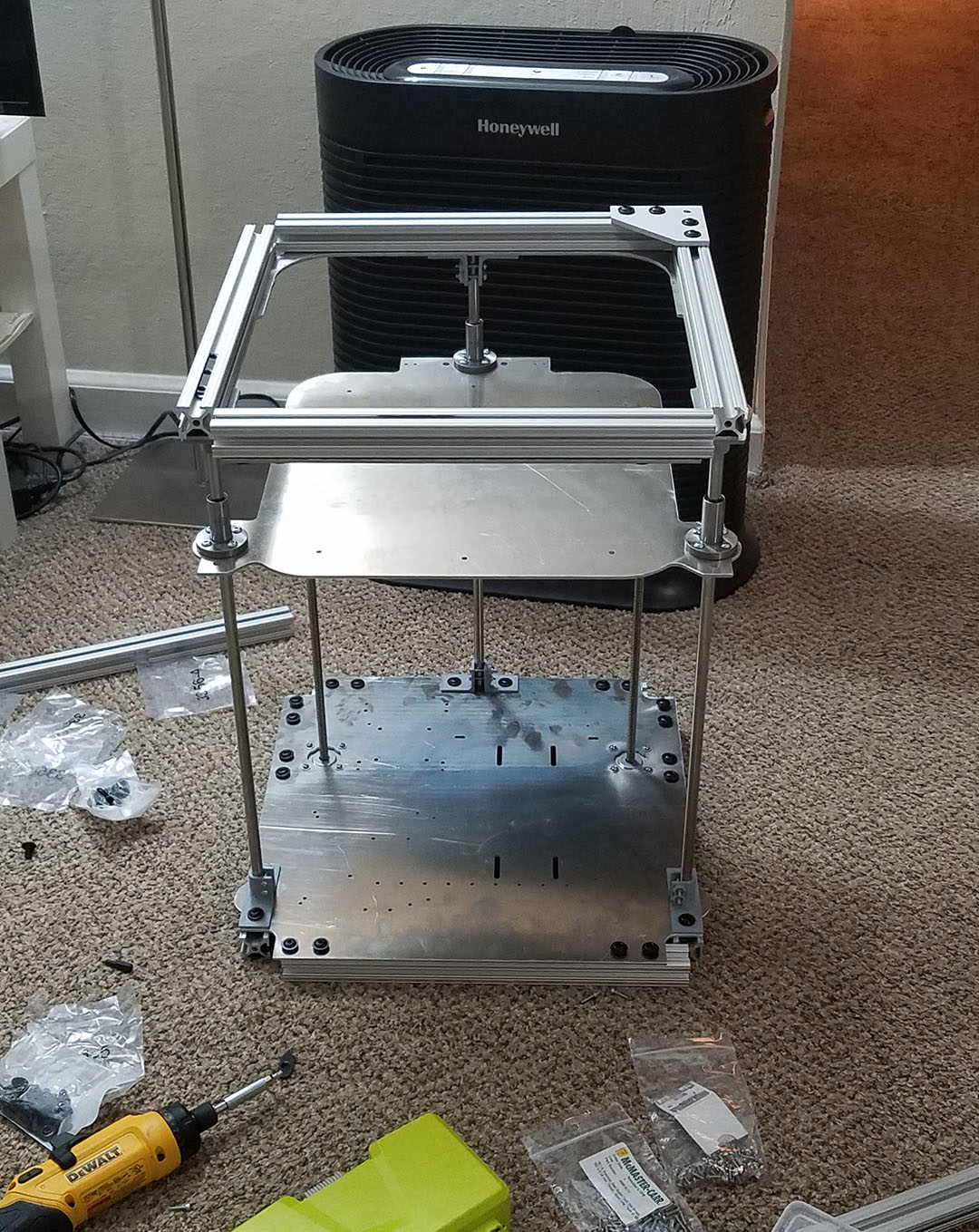
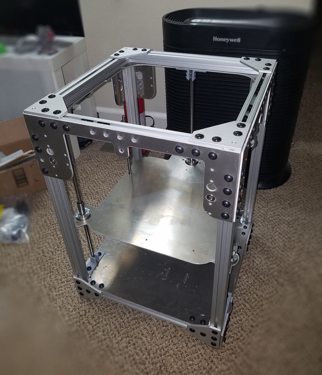
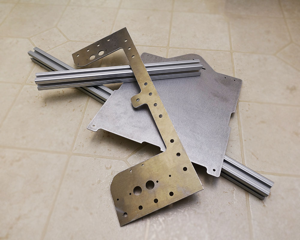
The frame is mainly constructed with T-slotted aluminum beams and aluminum plates cut via waterjet. Getting custom cut-to-length beams and waterjet’ed parts is pretty cheap and easy for me. McMaster-Carr will do custom length beams and I typically use Big Blue Saw for my waterjet cut parts.
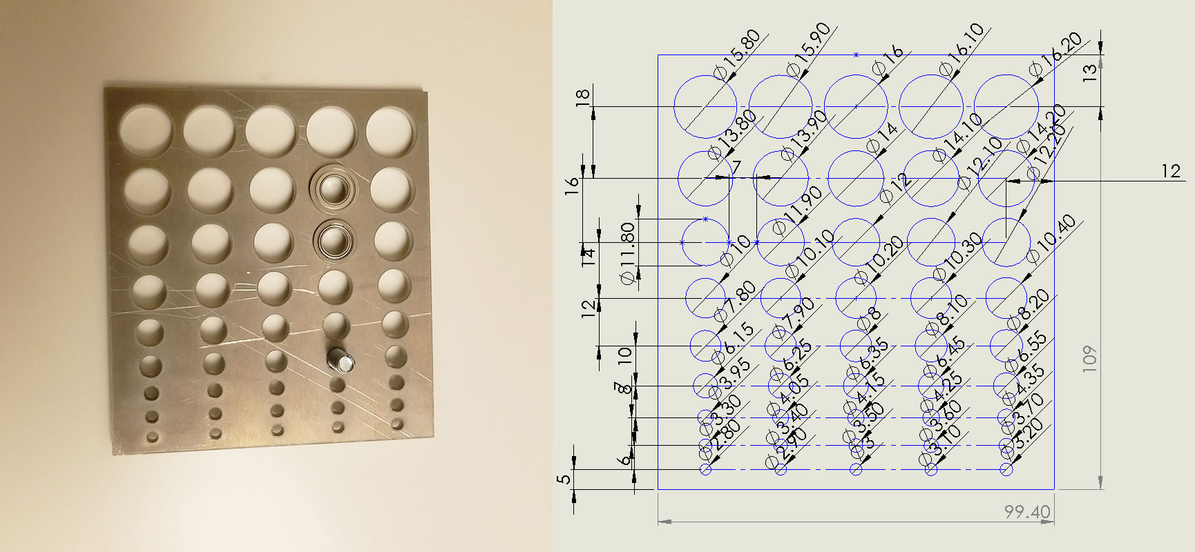
One problem with waterjet cutting is the slightly unpredictable taper and kerf of the cut. I needed bearings and screws to fit in perfectly (reasons explained later). To achieve the best accuracy with least effort, I first obtained some test cuts of circles that incremented in size by 0.1mm, and did some test fits of my bearings and screws so I can choose the best fitting hole size.
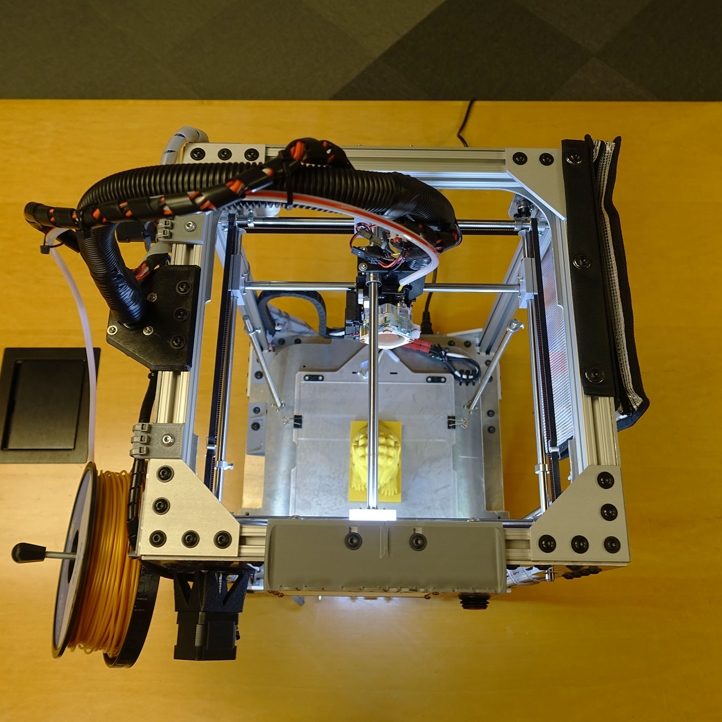
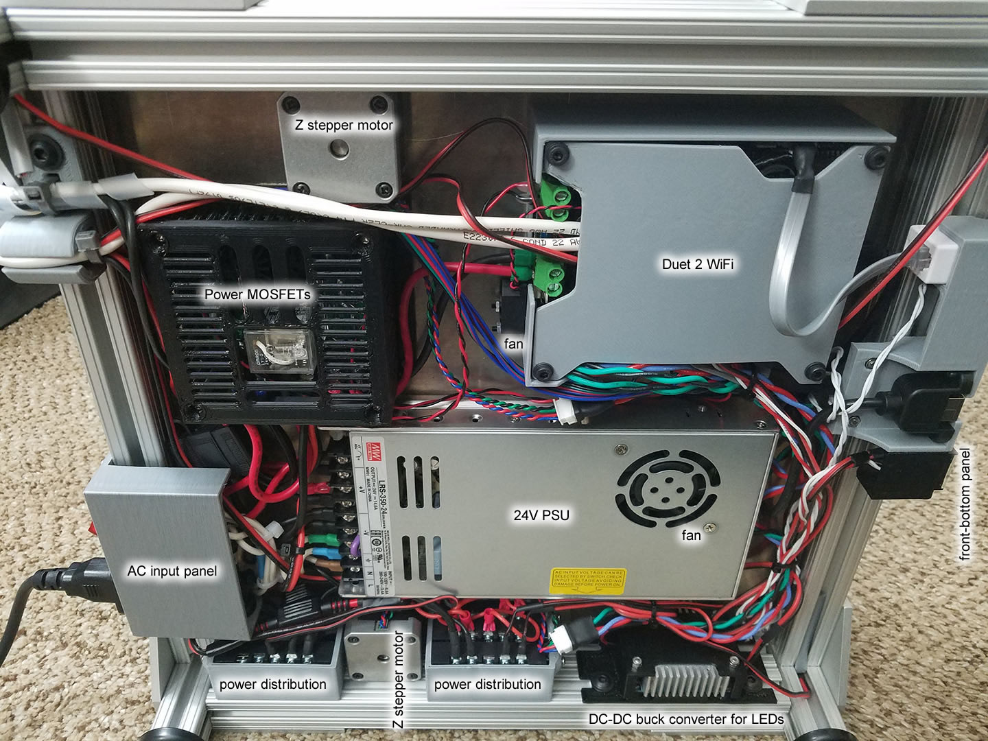
All the electronics are hidden under the bottom plate. This means that I can flip the printer upside down and then the electronics can be worked on as if it was a table.
Gantry
Sliding Blocks
Sliding Blocks
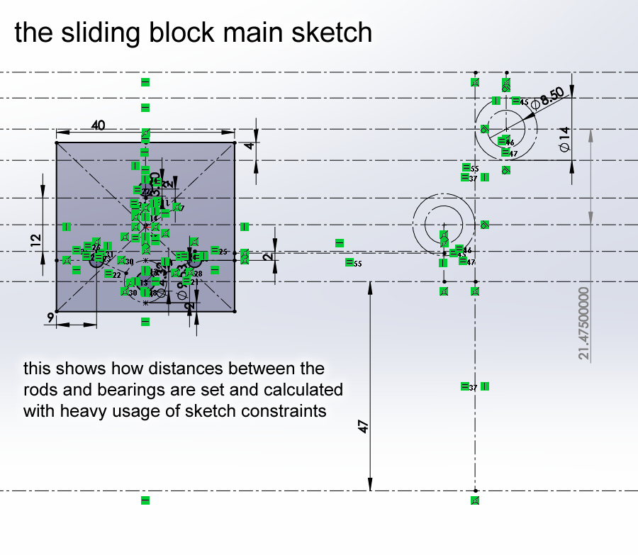
I love the Ultimaker 2’s X-Y gantry style (not sure if it is technically a gantry). My own design derives heavily from this style but uses different rod sizes and I designed my own sliding blocks. The sliding blocks of the Ultimaker 2 uses a snap-in cavity to hold the printhead rods, while my design uses a screw and rods that have internal threads at both ends. My design is 3D printed out of plastic (Ultimaker 2 used aluminum) so I was worried about repeated disassembly wearing out any sort of friction-held components, hence why I decided to use screws instead. My design is heavier because this decision made the rods thicker, but it also means my design is more sturdy.
The Ultimaker 2’s sliding blocks also integrates springs internally. My design does not, but it does feature a screw to tighten up the belt during assembly, and external springs to keep belt tension. This is because the Ultimaker 2’s assembly steps are different from my own, Ultimaker is assembled with the panels put on last, while my assembly steps are to put the frame together first. If I were to adopt the Ultimaker’s assembly steps, I would be fighting spring tension during assembly. My assembly steps are different because I need to do many kinds of design verification between assembly steps, whereas the Ultimaker is a tried-and-true product that has an optimized manufacturing process.
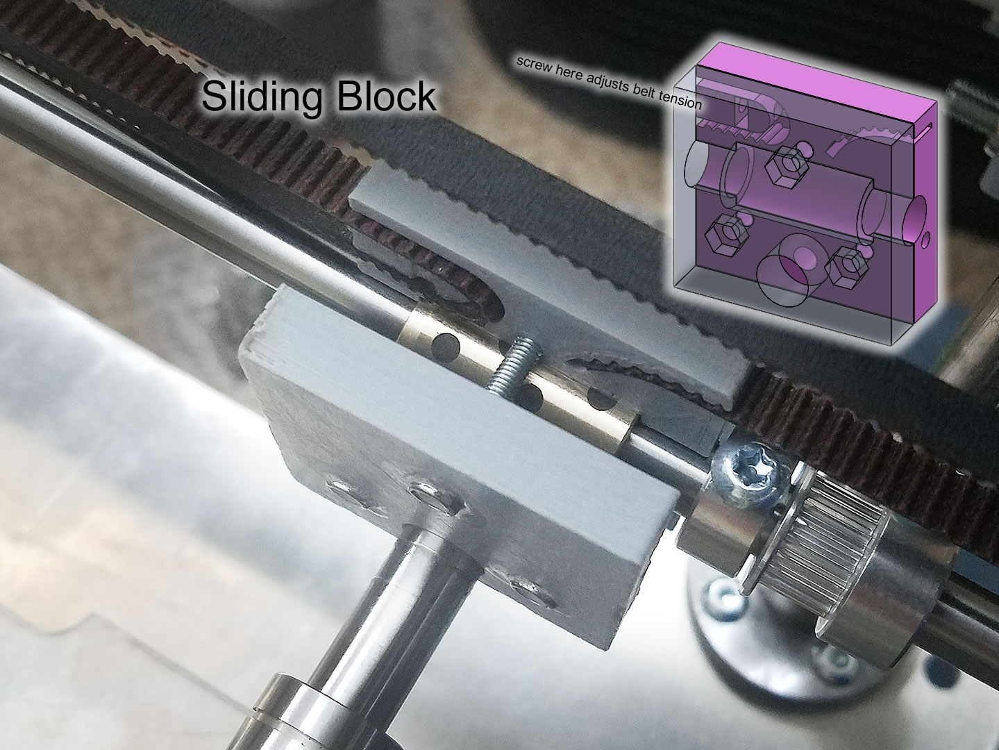
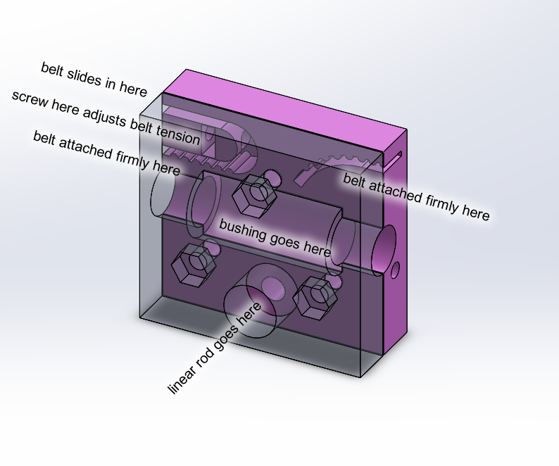
The bushing inside is a brass and graphite self-lubricating bushing purchased from Misumi.
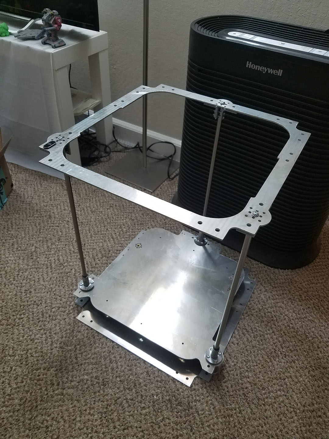
Axis Alignment
I was wondering how I can keep my two X axis rods and two Y axis rods perfectly parallel and also spaced apart perfectly. Most other similar cheap designs simply use 3D printed bearing holders and you kinda just throw it together and adjust if needed. I don’t like that idea at all. Instead, I got large aluminum plates with holes for ball bearings cut into them with waterjet cutting, this means the bearings are spaced apart correctly within 0.1mm tolerance, on all 4 side.
For the Z axis rods, the same idea is used. These rods don’t spin. I chose to use rods with ends that are internally threaded, aluminum plates for the top and bottom of the printer are waterjet cut with holes in the places for screws that anchor the rods. 3D printed shaft supports are retrofitted to give additional support. (I could buy shaft supports but they are more expensive than bearings…)
Belt Stretch
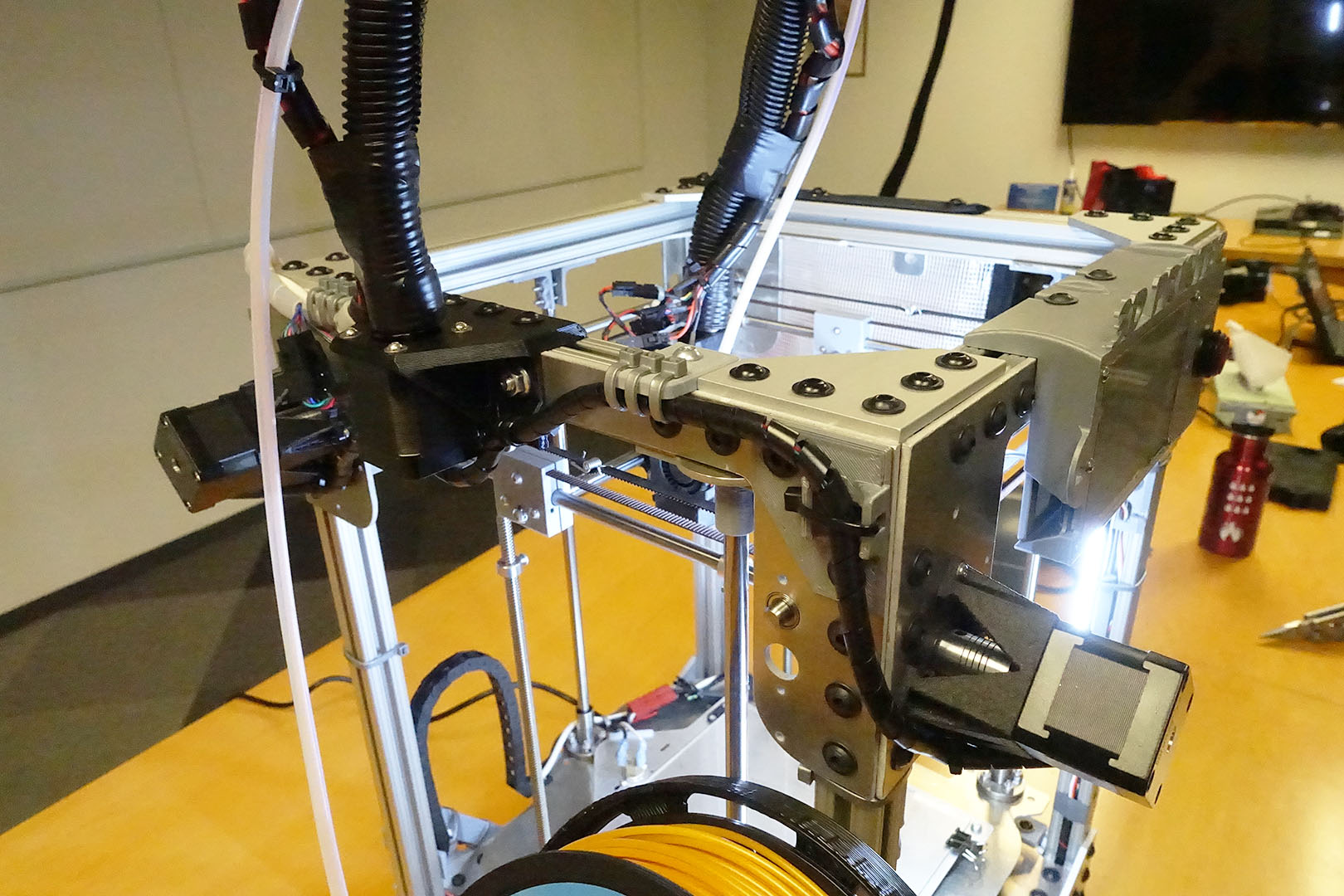
The X and Y stepper motors are mounted directly to the rods they spin, instead of through a small loop of belt (such as on the Ultimaker). This simply means there is one less belt to stretch for each axis. It also means the motor must stick out, instead of hidden inside the printer, so my printer looks a bit uglier. I can live with that sacrifice.
With the gantry style, there are actually two belts per axis. This is obviously better than one belt per axis like most other printers. Plus, each belt has its own tensioner spring.
All of this means, for the life of the printer, I should never have to tighten any belts as a maintenance step.
Fun fact, when Filastruder started to stock Gates brand belts, I got excited enough to pre-order it for this project. These belts are fiberglass reinforced rubber and has a nylon fabric coating.
Research indicated that steel core belts are not able to handle the small pulley sizes required for a 3D printer. The steel strands will break from bending around the small diameter. Using a larger pulley means less print resolution.
Bed
Stability and Durability
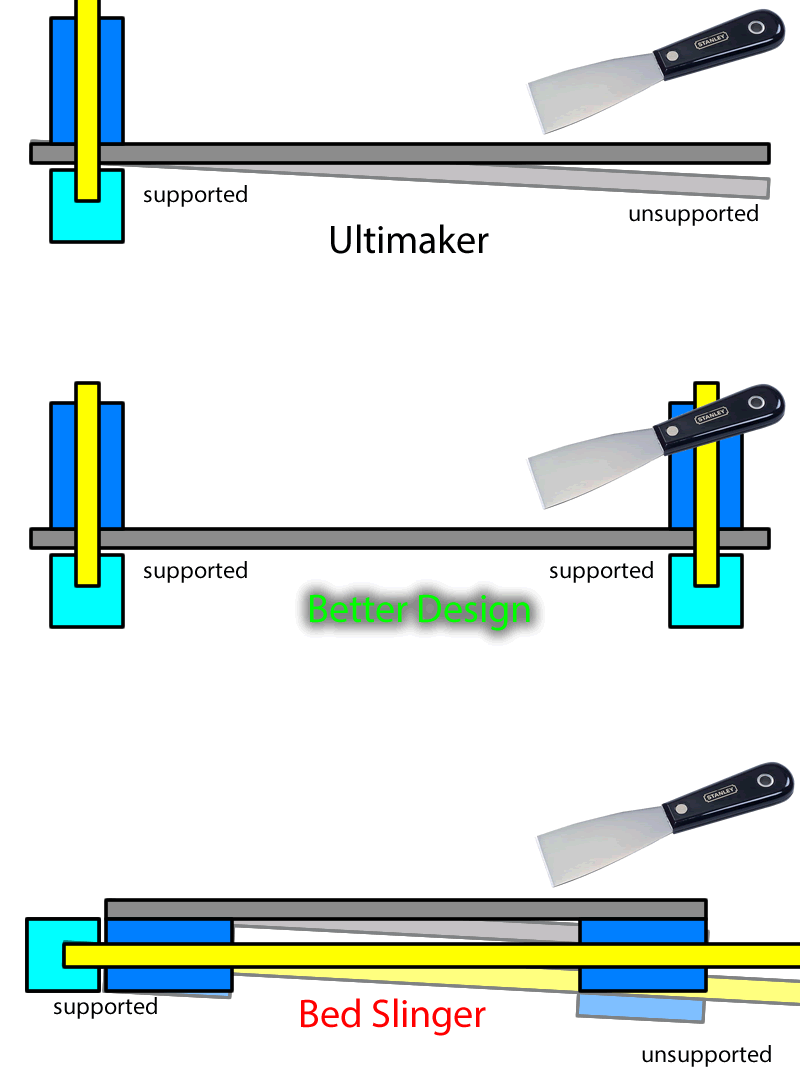
The bed style is one that is a platform that moves up and down in the Z direction. The Ultimaker 2 design is the same style implemented with two linear rods in the rear and one leadscrew. The Prusa design is a “bed slinger” that moves the bed in the Z direction. My design uses 3 linear rods and two leadscrews. This design decision is made due to the way I prefer to remove my prints from the Ultimaker 2’s glass bed, I have a razer-sharp-yet-stiff putty knife and I chisle off my prints with a lot of force in one single motion. I do not remove the glass frequently and I do not wash the glass frequently. This is a great workflow for me but it is not perfect, the fact that the bed is not supported from the front means I have been bending the bed downwards, which causes vibrations at the front of the printer when printing large heavy objects.
My design has one rod in the back and two rods in the front, which allows me to add some support at the front such that the force is absorbed directly into the frame of the printer.
My usage style is definitely not recommended on a “bed slinger” design, because the force would be transmitted into the middle of the rods carrying the bed, which risks bending the rods. This is probably one of the many reasons the Prusa features a magnetically removable steel bed, to encourage people to remove the bed before removing the print with force.
“Bed slinger” printer beds are heavy to move and the problem worsens during the print as the print becomes heavier, the larger mass means more belt stretching, resulting in ringing artifacts. This is usually resolved by tuning jerk and acceleration settings but doing so on a 8-bit microcontroller circuit has other repercussions.
A stationary bed is way better for tall objects, and objects that may have poor bottom adhesion. If the bed moves, then the printed object has a high risk of tipping over. Also, a moving bed means it is difficult to take good videos (or time-lapse videos) of the printer.
My design also minimizes the chances of encountering Z-wobble. From all my research, Z-wobble (or Z-banding) is a combination of a loose frame, and leadscrews that are attached by couplers. My frame is a very sturdy aluminum box, as opposed to an upside-down-T. My leadscrews are integrated directly into the stepper motors, without using any shaft couplers. And the final bit of stability obviously comes from the fact that I am using three rods in three corners of the bed.
Weight Distribution
My setup has two front vertical rod, one rear vertical rod, and two leadscrews in the middle. The bed plate has vertical linear bearings that are mounted in a position that gives them minimum friction. For this bed design, some thought has been put into where the center of gravity is. If the lead-nut is placed aligned with the center of gravity, there’s a chance that the whole bed will see-saw about the lead-nut, and possibly vibrate excessively.
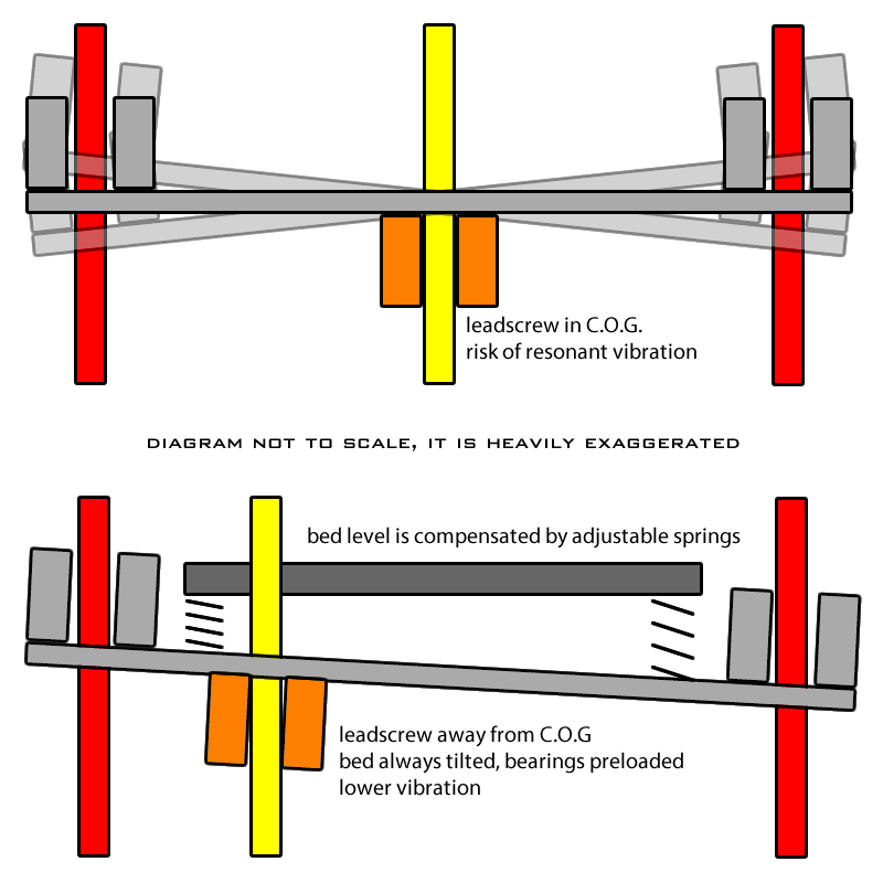
Having the leadscrews offset from the center of gravity would give the bed a moment load but this doesn’t matter because the bed is moving only fractions of a millimeter every few seconds or minutes.
Bed Leveling
“Bed slinger” printer beds are not easy to keep level without the assistance from sensors, and while sensors have somewhat caught up, they add another failure point and unnecessary complexity. Wouldn’t it be great if I can avoid this headache… I have no trouble adjusting the bed level of my Ultimaker 2 and it never needs releveling unless I do something special. While the first layer is being printed, my eyes watch where the line is too thin or too thick, and my fingers are on the knob making adjustments to the bed level. This is impossible if the bed is slinging around, and using the “slide a paper under the nozzle” method is way less versatile because you can’t adjust for extra “squish” as easily. Also using glass means I do not need any sort of “mesh leveling algorithm”, which is necessary for any sort of metal bed, which can flex (from repeated bending) or bulge (heating, uneven heating).
(this also avoids the need for “live Z adjust” or “baby stepping” inside the firmware)
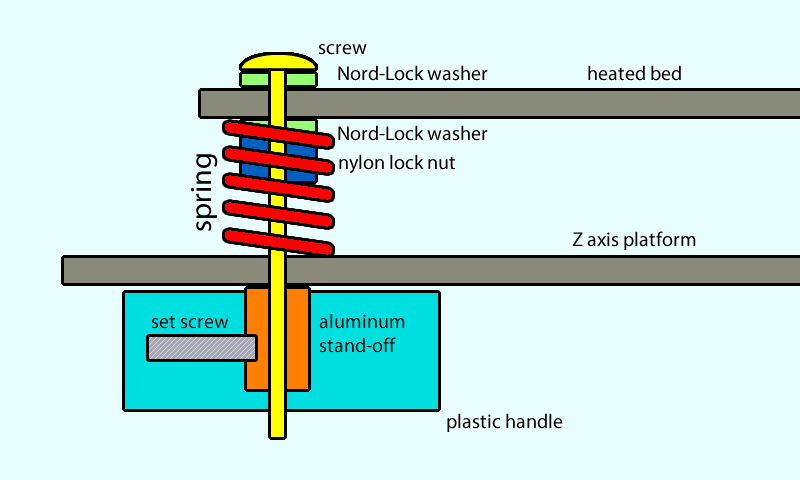
But, how do I replicate the Ultimaker 2’s design here? I had trouble finding similar components, and the ones available on Amazon/eBay/Aliexpress seemed a bit thinner than what I would’ve liked. I modeled out several combinations of screws, springs, nuts, wing-nuts, thumb-nuts, etc… in the end, I settled on a design that uses a #8-32 screw, Nord-Lock washers and nylock nuts to keep it from spinning, and a custom 3D printed knob. The knob has a 1/2″ long and extra wide hexagonal standoff embedded inside. This combination meant that I had a extremely rigid print bed with high tension springs, but I can easily and smoothly adjust the spring tension because the 3D printed knob has a much larger diameter than what could’ve been achieved with simply wing-nuts or thumb-nuts.
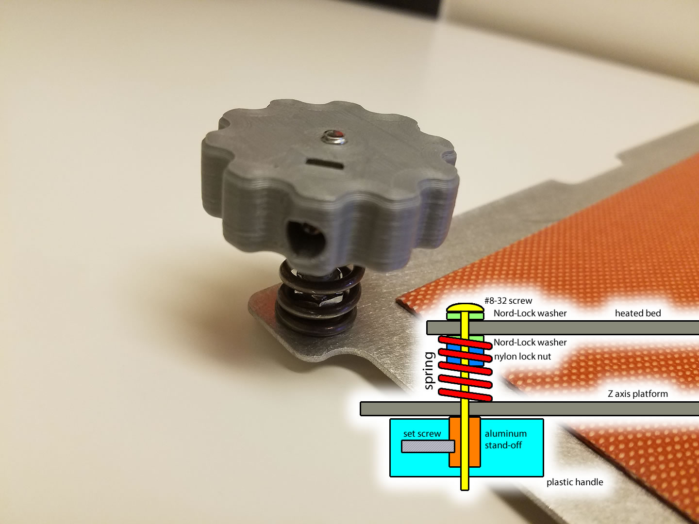
Yes, I understand that the large knobs are not a new idea, but I am proud of this one because it worked perfectly on the first try, looks cool, and is built in a very durable way.
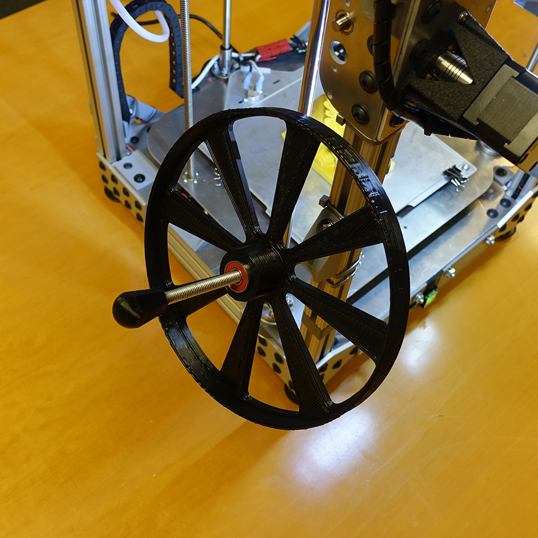
Twin Leadscrew Sync
While the Z axis does have a limit switch, it’s mounted on one side as close to the lead-nut as possible. This leaves the possibility of the other leadscrew not being in sync with the first, causing the bed to become slanted.
This problem is solved by using a limit switch with a massive amount of travel, and shaft collars on the leadscrew to physically set a stopping point for both lead-nuts. The homing script will quickly lower the the bed to the point where the limit switch closes, and then slowly lower it more until both lead-nut hits both shaft collars.
This is because I wanted an elegant and quiet homing operation, using two leadscrews with stall-detection is insanely unreliable, and also, the current firmware version of RepRapFirmware does not have gcode scripting yet. So I am using a limit switch kind of acting as a if-statement, and it prevents the printer having to make a lot of “jammed stepper” noise because the switch over-travel is fairly short.
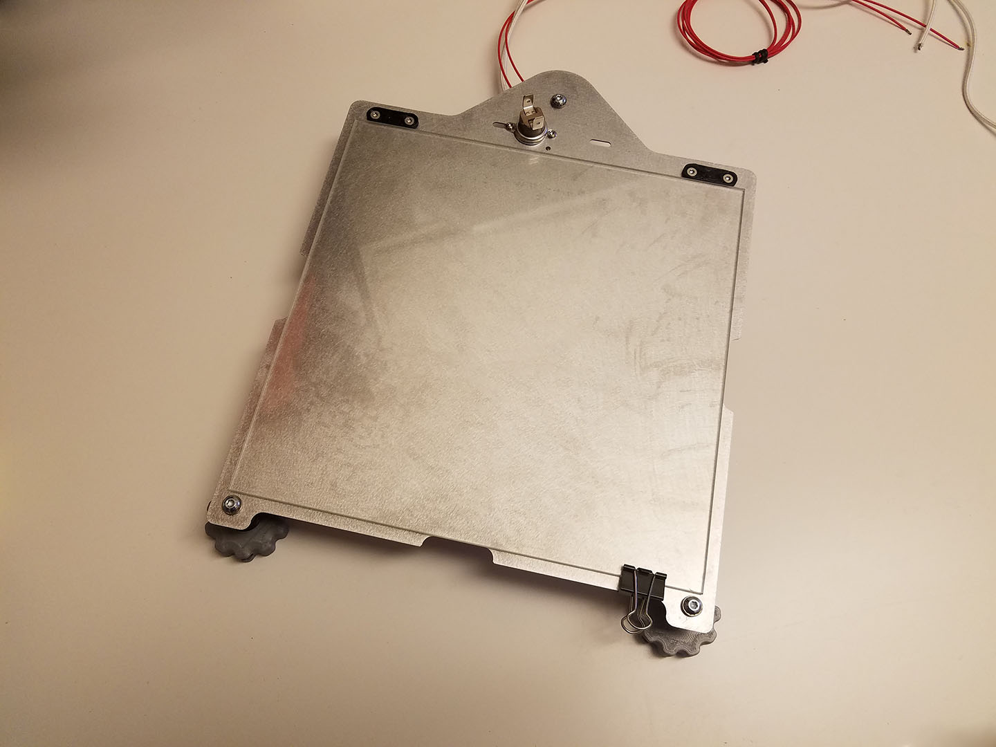
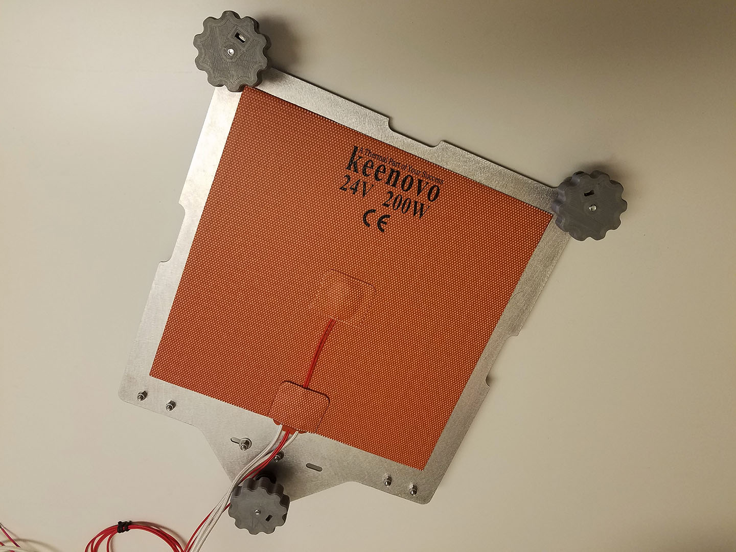
Bed Heating
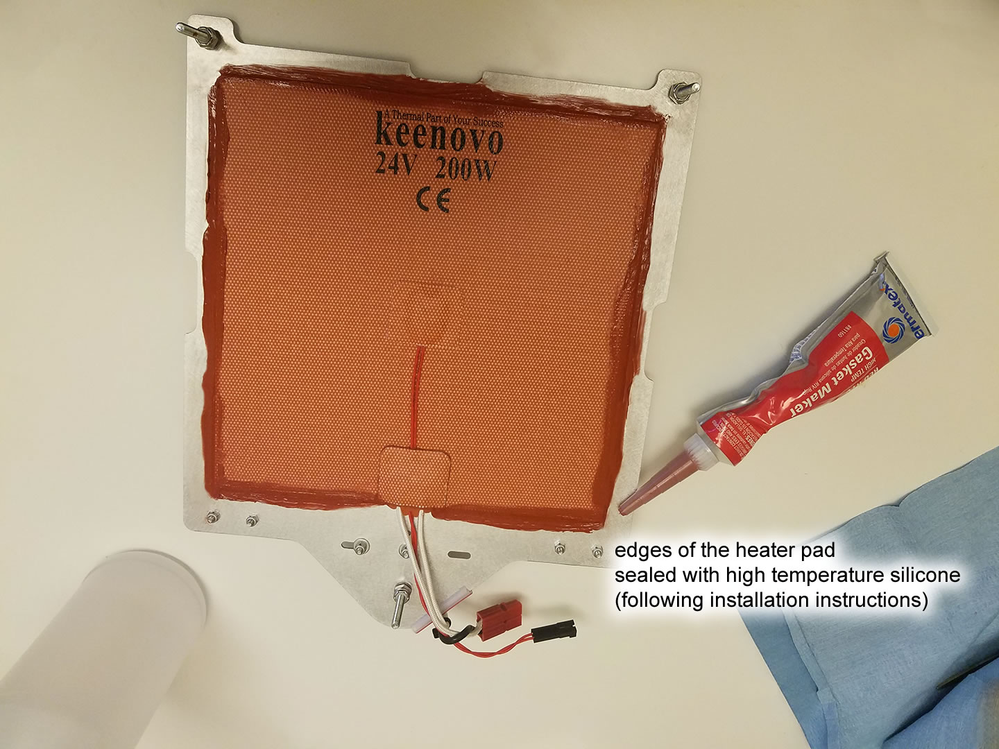
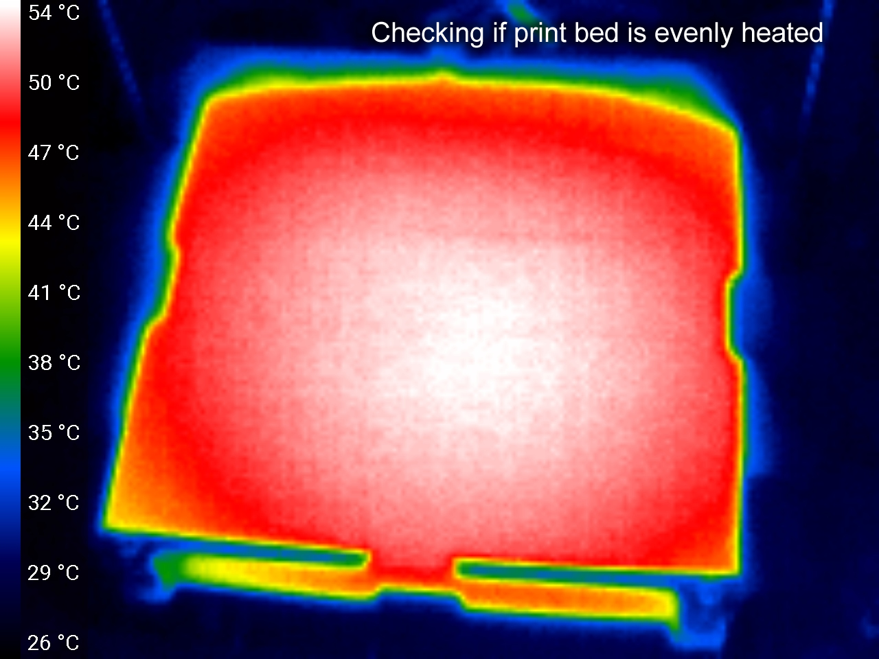
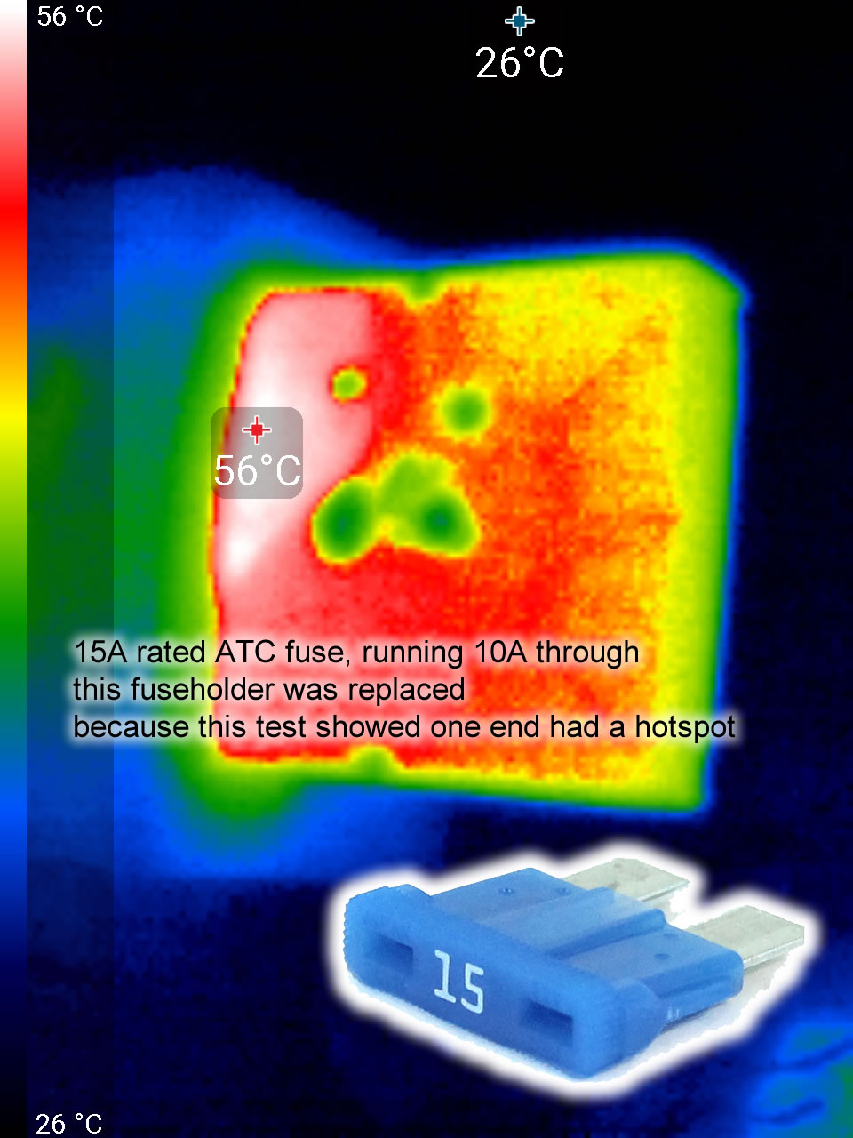
I used a 200W 24V silicone heating pad. The waterjet cut bed has additional holes for thermal fuses and other sensors.
Here’s a thermal image to show how evenly it is heated:
Glass Plate Clips
The glass plate is held in place from the front and sides by ordinary binder clips. I am not annoyed by these clips because I do not remove the glass very often. Plus, it is difficult to find a good permanent clipping solution that is suitable for a custom 3D printer.
The back of the glass is held against a back-stop that is secured with screws, this is meant to absorb the hits from my putty knife while minimizing the chance of cracking the glass.
Electronics
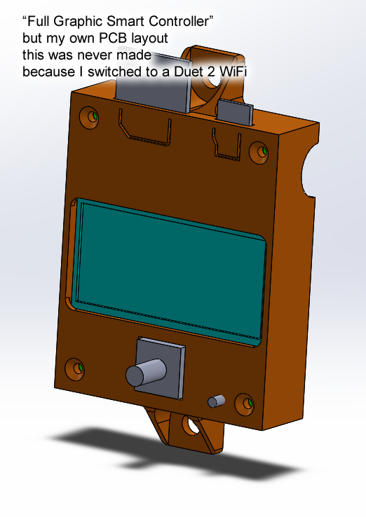
Controller
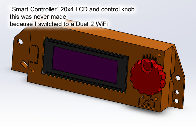
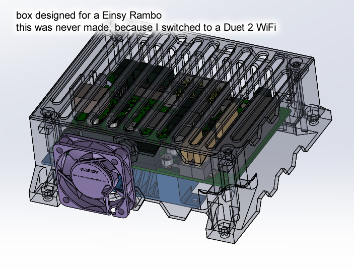
I originally wanted to use an Einsy RAMBo so I could just use Prusa i3 MK3 firmware. But as I decided to not include any sensors, I decided to use a Duet 2 WiFi instead.
It has Trinamic stepper motor drivers and a 32 bit microcontroller, which gives it an edge over most other controller circuits currently out there.
8 bit microcontrollers have processing limitations that can only be mitigated with more processing power. There are plenty of resources out there that explains this in more depth, such as https://3dprinting.stackexchange.com/questions/542/what-is-the-benefit-of-using-an-arm-based-electronics
The Duet PCB is mounted a bit high and there’s a small cooling fan that blows air to the underside of the PCB, directly across the bottoms of the stepper driver ICs. This gives me a lot of headroom in the current limit settings, I can run my stepper motors at their rated maximum limit without worrying about any overheating. (actually, the Duet documentation only recommended active air cooling for 2A and above, so me using 1.8A and under with a cooling fan is kind of overkill)
The current limits are set digitally, not via a trimpot like most RAMPS boards. It’s more convenient and definitely safer. (tuning stepper current on RAMPS requires you to ground your screwdriver and such, and those trimpots are susceptible to being overturned)
Stall Detection
One thing I loved about the Prusa is how it uses Trinamic stepper motor drivers, and takes advantage of the stall detection feature of those motor drivers. The stall detection is used as an alternative to using limit switches to implement end-stops (for homing) on each axis. The Prusa can also resume from power-outage and layer shifting (detecting this requires stall detection), which means the homing with stall detection is very reliable, consistent and repeatable. This is why I also chose to use Trinamic chips, a bit beefier, and I am also using the stall detection in the same way.
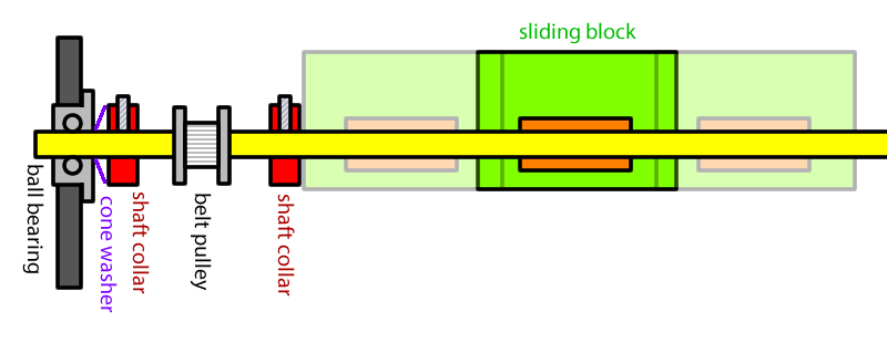
Using stall detection on a gantry style similar to the Ultimaker requires special attention paid to how the rods are installed. Shaft collars are used to stop the sliding blocks, so the force will be a thrust force transmitted along the rod. Another shaft collar is installed up against the ball bearing (with a flange, of course) at the end of each rod. There is also a cone washer to add some tension to the system so that the rod does not ever shift.
The cone washer does mean that there’s some compression when the shaft collar is hit but the belt should be a bigger concern in this regard. The ball bearing is experiencing some extra thrust load every time the shaft collar is hit. I cannot predict whether or not this will become a problem yet, time will tell.
The belt will experience some stretching when the stop is hit. I am aware of this and thus I’ve placed the stops at the end where the belt will stretch the least amount, meaning near the motor.
The motors needs to be spinning at a fast rate for stall detection to work, but acceleration must be slow to not accidentally trigger the stall detection. This means the position must be far enough away from the stopper so there’s enough room to accelerate, and a lot of trial-and-error tuning involved.
The Prusa i3 MK3 does not use this feature for the Z axis since it has a bed sensor. I refuse to add a bed sensor but I have a limit switch on the bottom of my Z axis just in case stall detection doesn’t work well on the Z axis.
Beefy MOSFETs
As the design progressed, I know roughly how big the bed is. The most powerful heater for that size is 200W, at 24V. I really didn’t want to go to a 120VAC powered bed to avoid SSRs, grounding, and other safety issues.
200W is pushing the limits of the Duet WiFi’s PCB. The hardware designer of that PCB explicitly stated that it needs a hack before it can truly handle the amount of current draw required. (the MOSFETs and connectors on the Duet is properly rated, but a trace on the PCB is a bit too thin)
In the end, I designed my own MOSFET circuit board, with the goal of overengineering-on-purpose. The MOSFETs are Infineon Technologies (International Rectifier) IRFP4468PBF:
- rated for about 200A with about 2 milliohms of RDS while on
- purchased from Digikey to avoid counterfeits
- TO-247 package with the biggest heatsink I can fit in the space constraints
- The gates are controlled by opto-isolators
- There are TVS and Zener diodes everywhere to protect these expensive MOSFETs
- Plus flyback diodes just in case an inductive load is connected
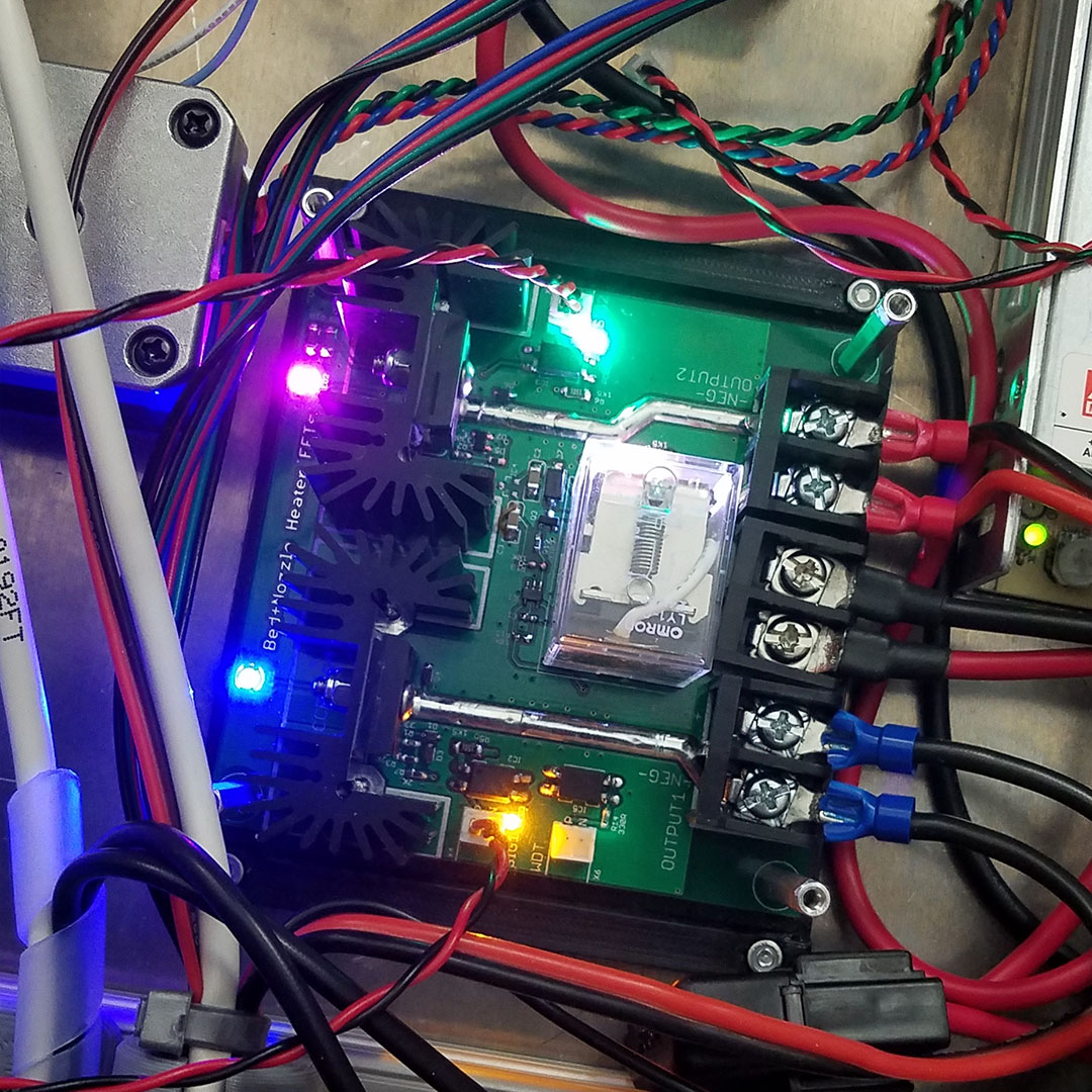
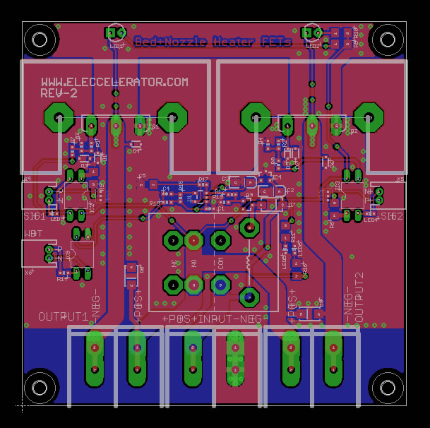
There’s even a safety watchdog circuit on there that uses a physical relay to cut power. But that section of the circuit was a design failure, I’ll talk about that later.
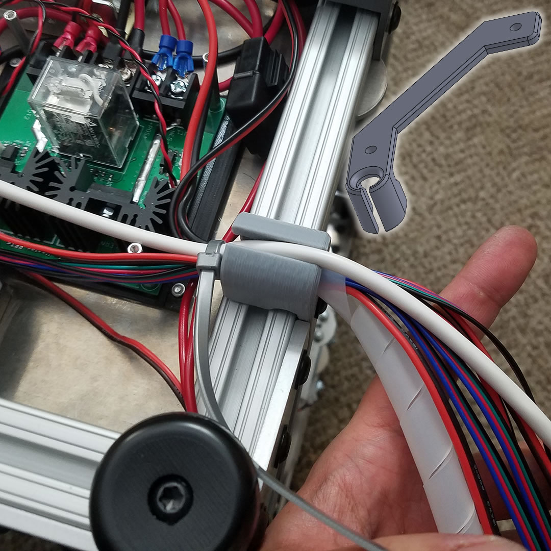
Wiring and Wire Management
A lot of silicone insulated wiring was used to minimize fire risk. They are also very flexible, which is good news for a design with a 2D moving printhead. The wires for the heated bed are hidden in a cable drag chain to minimize risks of damage.
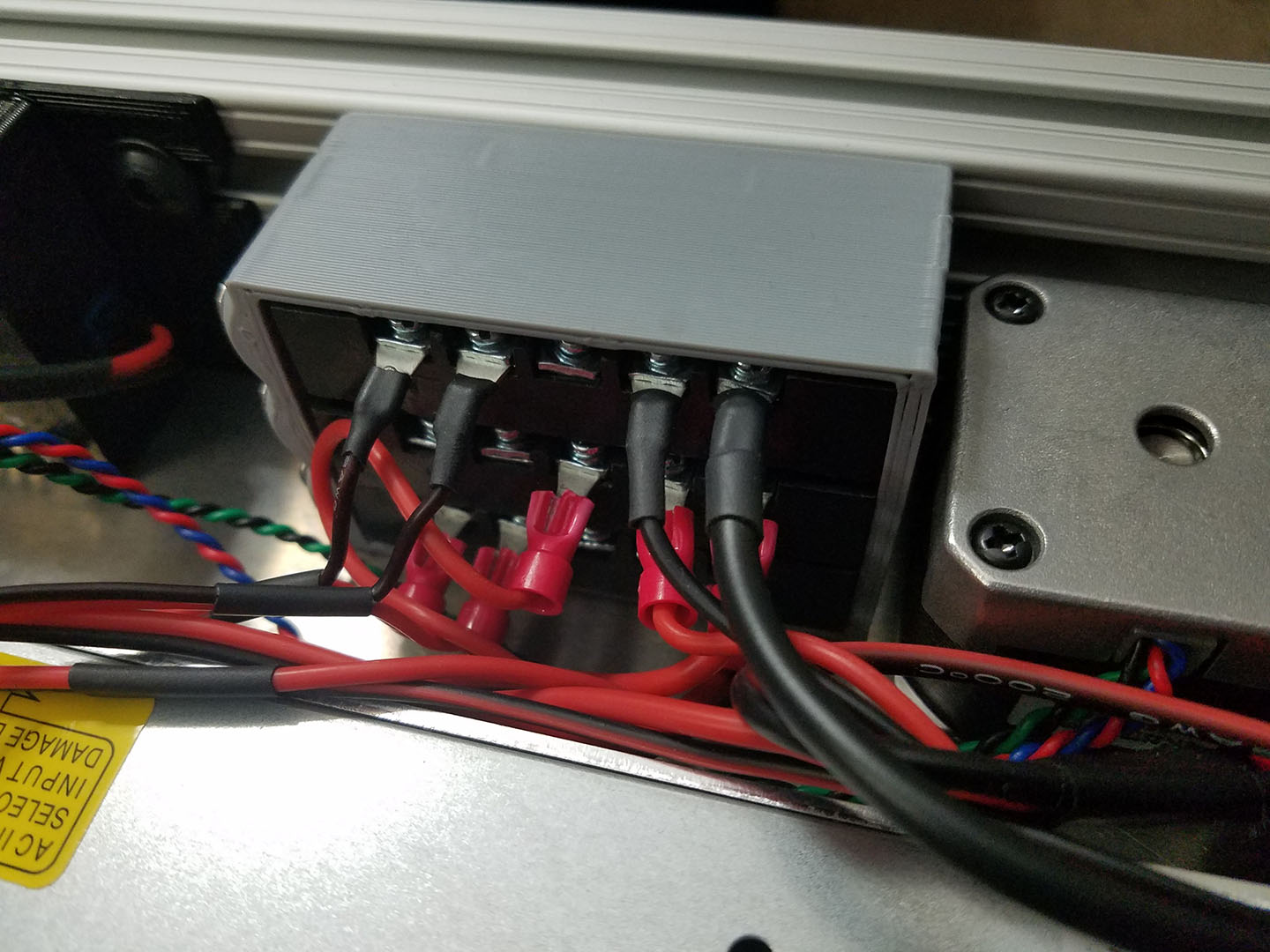
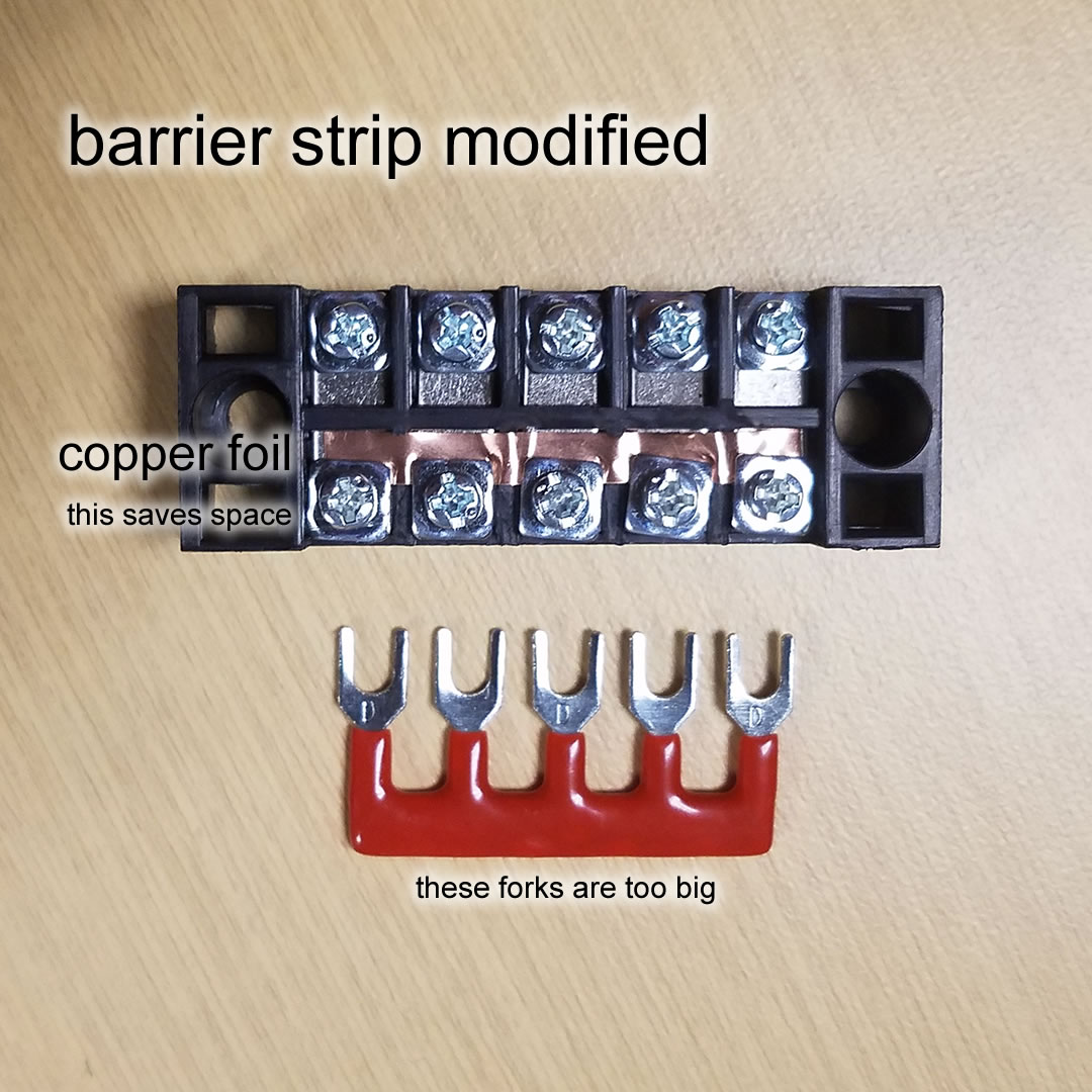
For modularity, 24V and 12V power rails are distributed using terminal barrier strips that have been modified. I came up with this trick using copper tape to make them smaller
The cables for sensors are 6 conductor and shielded, grounded at one end. I can’t do grounding at both ends because technically there’s no ground on the other end. Only 2 wires out of 6 are used, so 4 shielded wires are still available for future add-ons.
A ceramic fuse is used on the AC power input, and automotive fuses are used frequently on all the DC power wires.
Of course, appropriately rated connectors are used for all connections, and the connections are placed in the ideal places for best modularity.
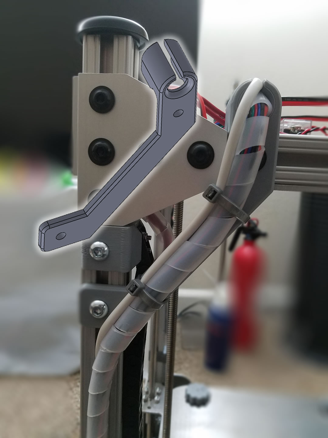
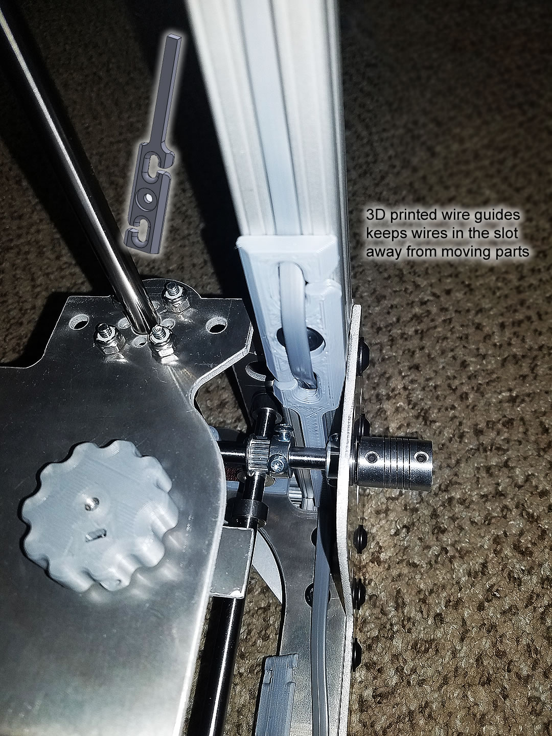
There are plenty of custom 3D printed pieces attached to the frame that are designed to guide wires around or even inside the aluminum frame. Near the gantry, there are pieces that protect the wires from touching the rotating components.
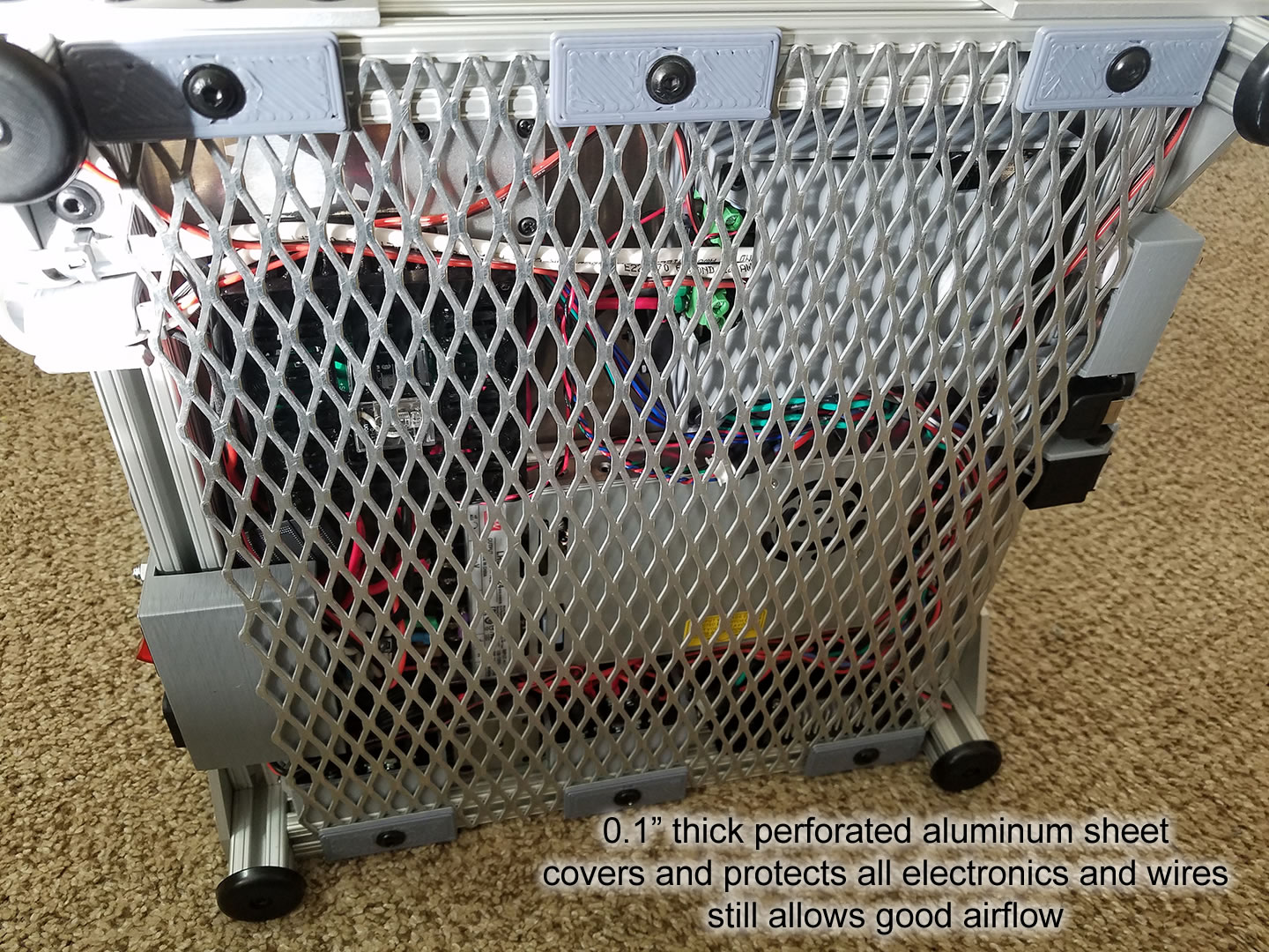
Finally, everything is neatly covered up with an aluminum panel, with perforations for air cooling.
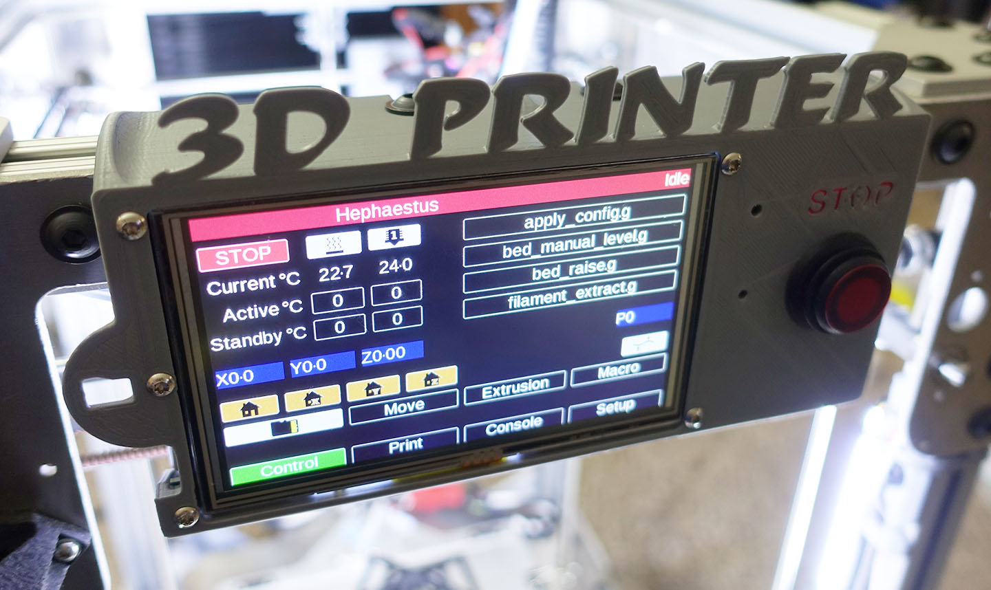
Control Panel
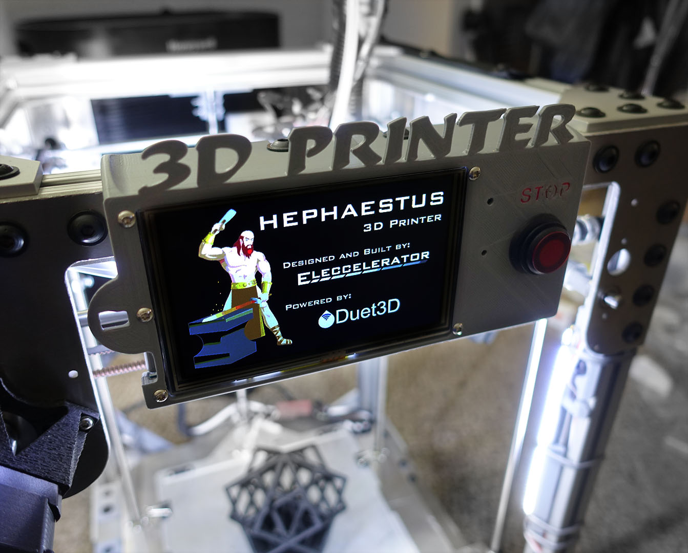
There is a bottom user panel and a top user panel. The top panel houses a PanelDue 5i, which is a touchscreen interface that directly interfaces with a Duet controller.
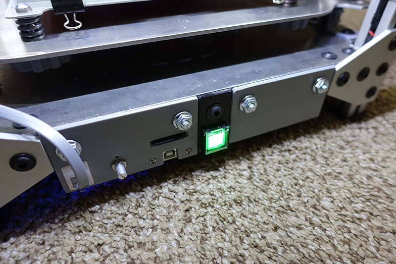
The bottom panel houses a beefy USB-B connector extended from the Duet PCB, a SD card slot (also extended from the Duet), and the potentiometer for adjusting the LED lighting.
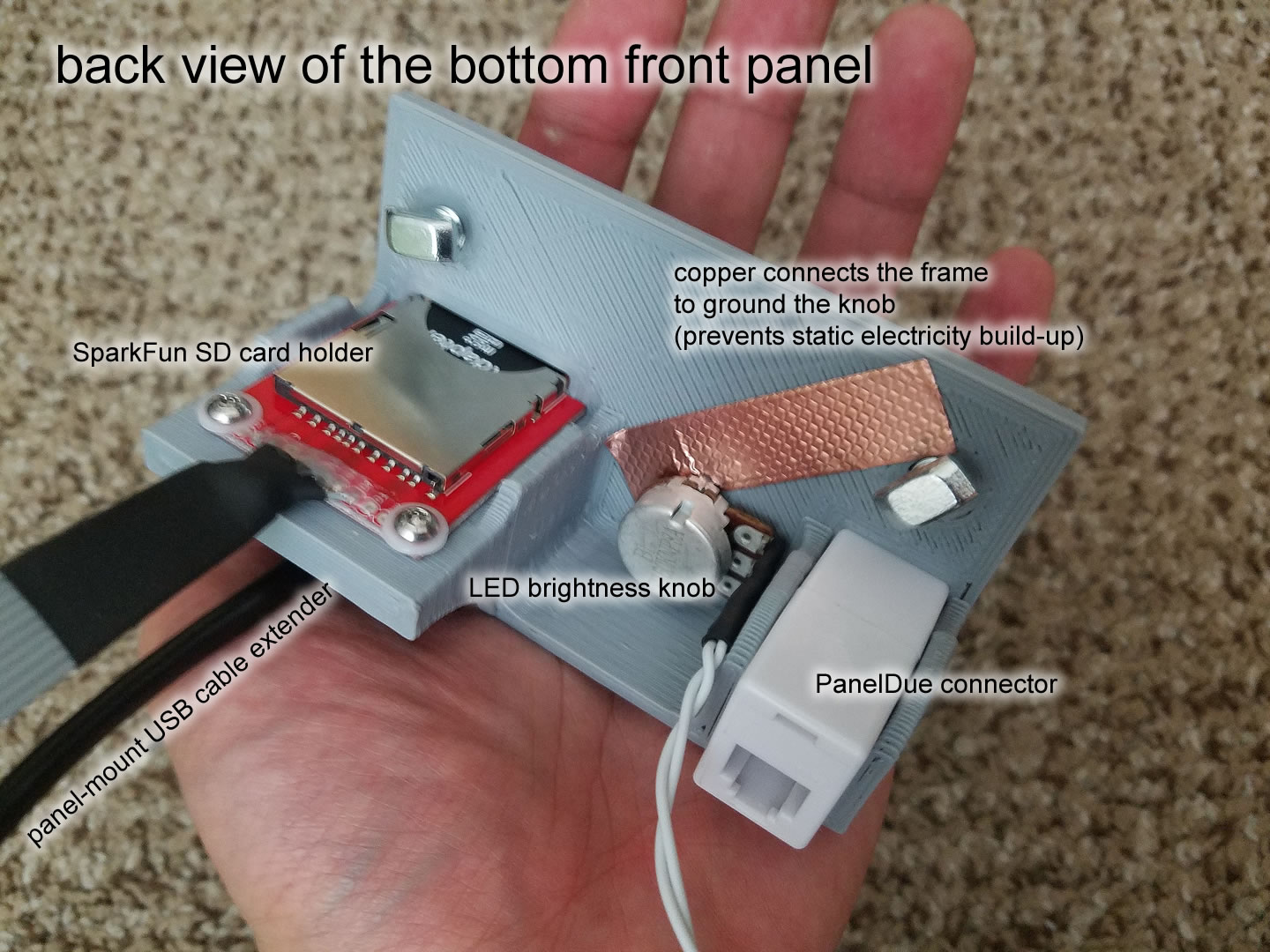
The PanelDue technically does have a microSD card holder but the distance between the Duet and the PaneDue is too long, the SPI signals would not survive and it creates an unacceptable stub for the entire SPI bus, which would’ve made the other SPI devices malfunction. This is why I added my own SD card slot on the bottom of the printer instead, the wires are much shorter this way.
The UART signals for the PanelDue can survive the long cable length, due to mainly the relatively slower signal, and the fact that no other devices are on that bus.
I did not mount the PanelDue on the bottom of the printer, because the bed will be lowered for me to remove the print, and I can’t let the panel be in the way of my putty knife.
Multipurpose Context Button
Late into the project, I added another button that’s multipurpose. I realized that the gcode macro capabilities of the Duet allows me to change what a button does on-the-fly.
For changing filament, the button means “stop extruder”, which means I can leave the printer to clean out the old filament out of the nozzle for a long time and press the button when the nozzle is extruding new filament. This is pretty simple, it’s simply as if it was the end-stop switch of the E axis. This is great since I can’t accomplish this with just the PanelDue.
During printing, it means “pause”. End-stops can be converted to a trigger that launches macros, so the E axis end-stop becomes a trigger for the pause macro when a print starts.
The button is also bi-colour LED illuminated. I used two of Duet’s PWM fan control pins to control these LEDs.
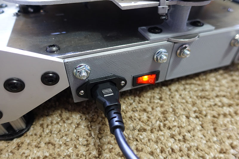
There is also a rear panel that is simply the AC power input, a power switch, and it houses a fuse for safety.
Power Supply
Mean Well LRS-350-24, purchased from Digi-Key to avoid counterfeits. 24V, 350W, actively cooled, low profile. The bottom of my printer actually has 2 inches of space so using a 1 inch tall PSU give it plenty of room to breath.
The mounting hole pattern on the bottom of the printer allows for similarly shaped PSU to be installed as well. I can easily change it to a fanless PSU, or a beefier unit with a fan.
I choose 24V because, well… the only advantage of a 12V system is that it’s cheaper. 24V systems heats faster with better thermal stability, motors can move faster (and easier to use stall detection with a higher voltage), and it works better with power-loss detection because the capacitors store more power.
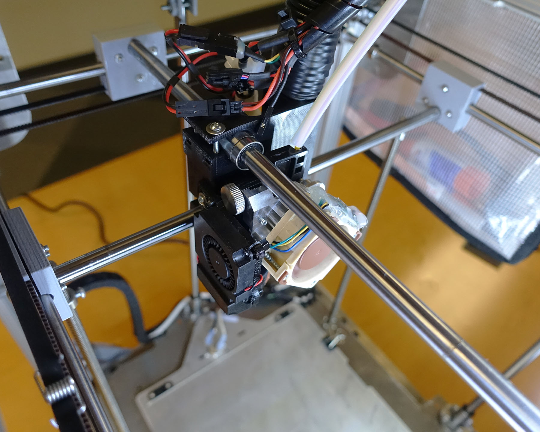
Extruder (aka printhead or toolhead)
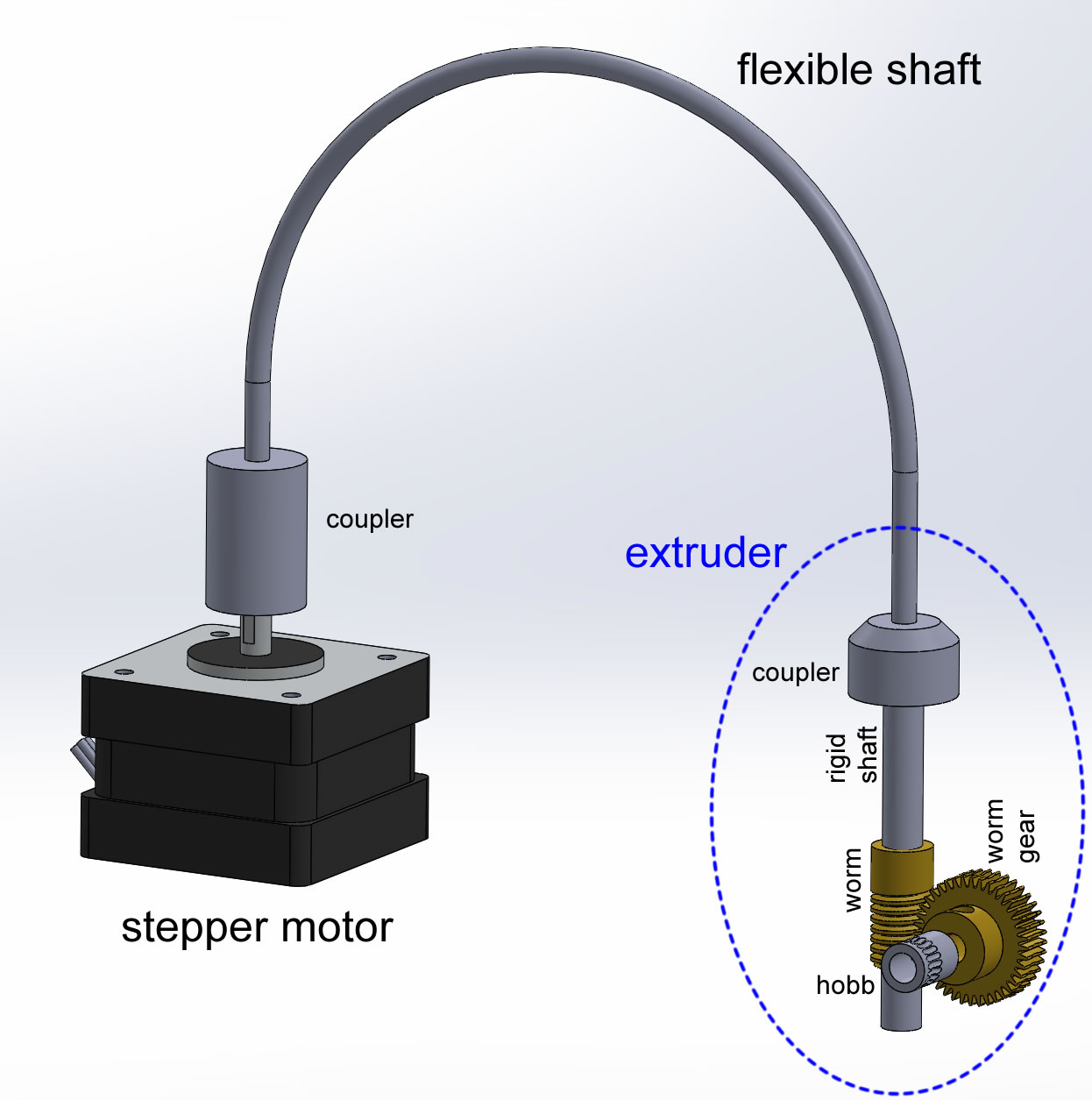
There are two different versions of the extruder. The first version (V1 henceforth) was completely designed by me, and the second version (V2 henceforth) was mostly an attachment for the E3D Titan Aero, which is what is currently being used. Both versions use a flexible shaft driven system inspired by Flex3Drive.
Flex3Drive Inspired System
The extruder design is inspired by the Flex3Drive system, which I already have implemented in the Ultimaker 2. It combines some advantages of a bowden style extruder with the advantages of a direct style extruder. It is technically a direct drive gear, with a heavy gear reduction, but the motor is mounted away from the gears, the rotational motion is transmitted by a flexible shaft. This means it’s lightweight to avoid belt stretching (and thus ringing artifacts), it can print flexible filament better (because there’s less room for the filament to buckle), it jams less and is more precise because of the gear reduction. This is why a CoreXY style or Delta style printer was not considered.
I have been a customer of Flex3Drive for many years and the guy who runs the business is great, providing prompt support, firmware updates, constantly improving his products and I’ve kinda been used as a beta tester. The problem is that recently I needed a replacement part and he kind of disappeared on me for a long time before responding. I can certainly see the difficulties with running a home business in a niche market within an already niche market so I am going to be understanding. The Flex3Drive system has some parts that I cannot obtain off-the-shelf, so my own implementation has to be less reliant on the Flex3Drive store.
The heat from the motor is never transmitted to the filament, so I can run this motor with as much electrical current as I want, giving me good speeds.
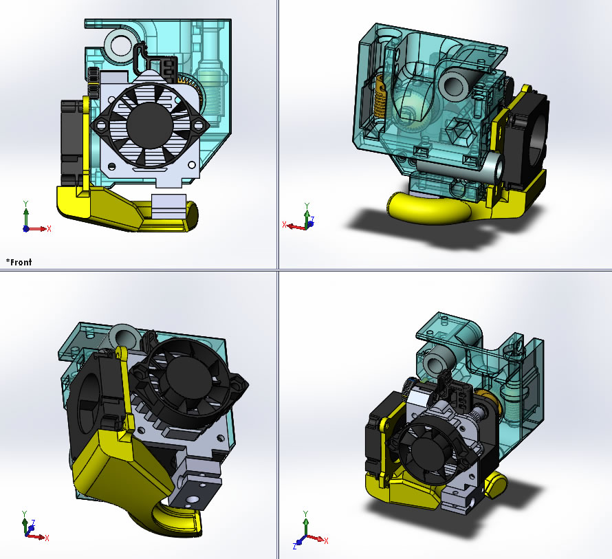
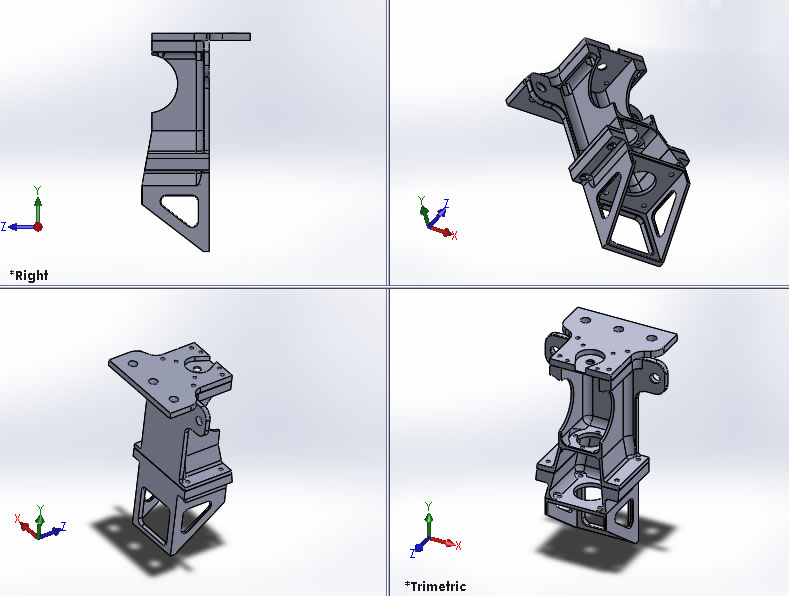
V2 Extruder Body
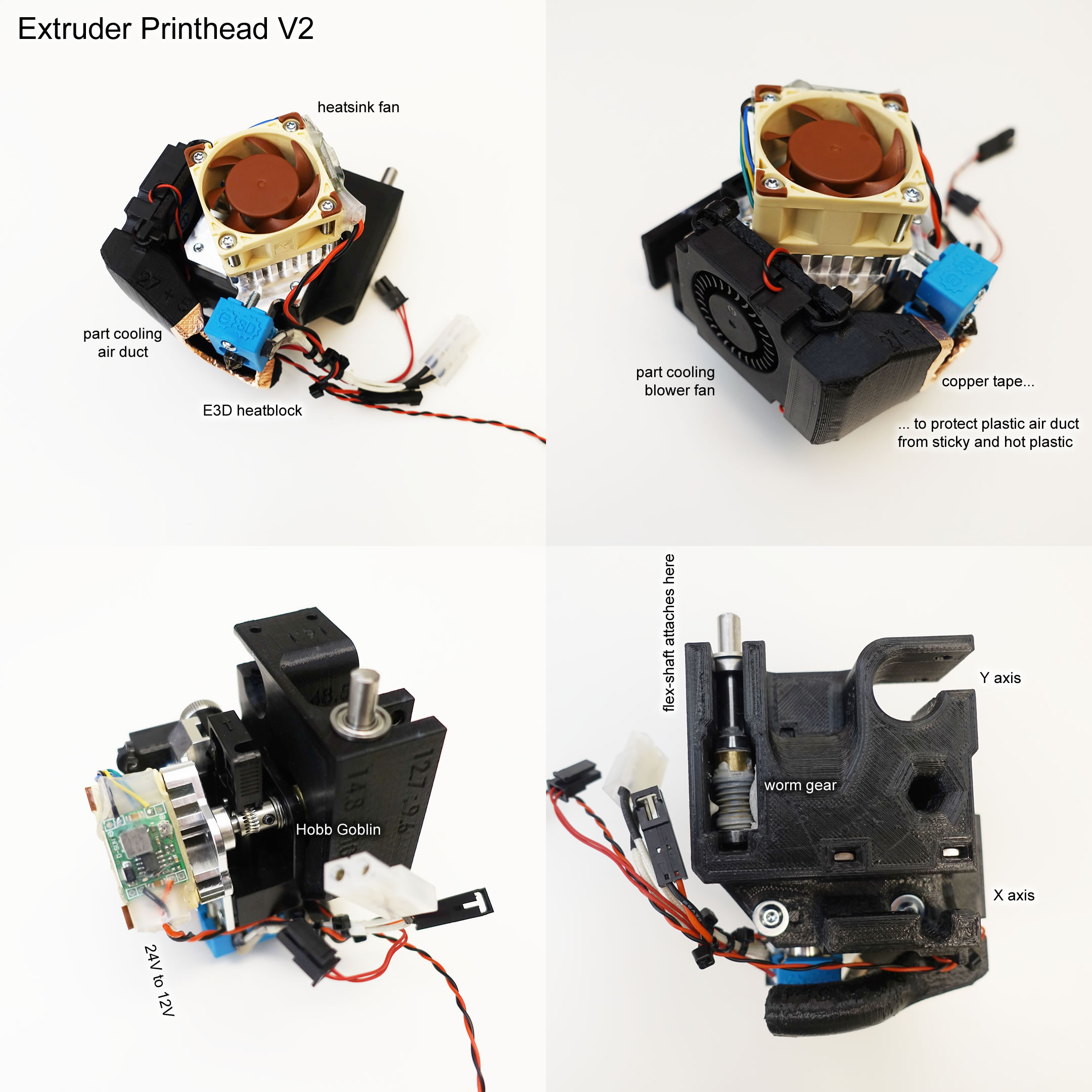
I decided to adapt the E3D Titan Aero to have a flexible shaft driven system. The actual Titan Aero already had a 3x gear reduction, which I cannot mix with the 40x reduction I already use or else it will be too slow. But the drive shaft on the Titan Aero is still a 5mm shaft so all I really needed to do is replaced the stock hobb that has the gear, with a different hobb without the gear, and extend the shaft where I can put my worm gear.
So I designed a square-ish housing that goes on the back of the Titan. It houses the worm drive train, and the two axis bearings. It is much much much simpler than the V1 design and the center of gravity was placed much better.
This design was created because I was trying to fix the problems on the V1 extruder (shown later), and realized I can improve upon it: the center-of-gravity placement, the assembly complexity, and risk of breakage during assembly. (I’ll discuss this in detail later)
This design is not perfect either, mainly because the Titan Aero is not suitable for any MMU feed system due to the way the tension lever is designed. I will use this printer and redesign the tension lever later if I ever do need to add a MMU feed.
For those who noticed that the screws don’t look secured in my pictures… It turns out that the Titan Aero has holes in it for M3 screws but they are the perfect size to be tapped with a #6-32 thread. I thread tapped the heatsink and used #6-32 screws with thread-locker.
The tension lever usually pivoted around a stepper motor, but since I have no motor, a simple 5mm rod is inserted between the heatsink and the 3D printed plastic body.
The Noctua 40x40x20mm fan replaces the stock 40x40x10mm fan. Longer M3 machine screws can be used instead of the stock sheet metal screws, the heatsink can be threaded with M3 threads easily.
V1 Extruder Body
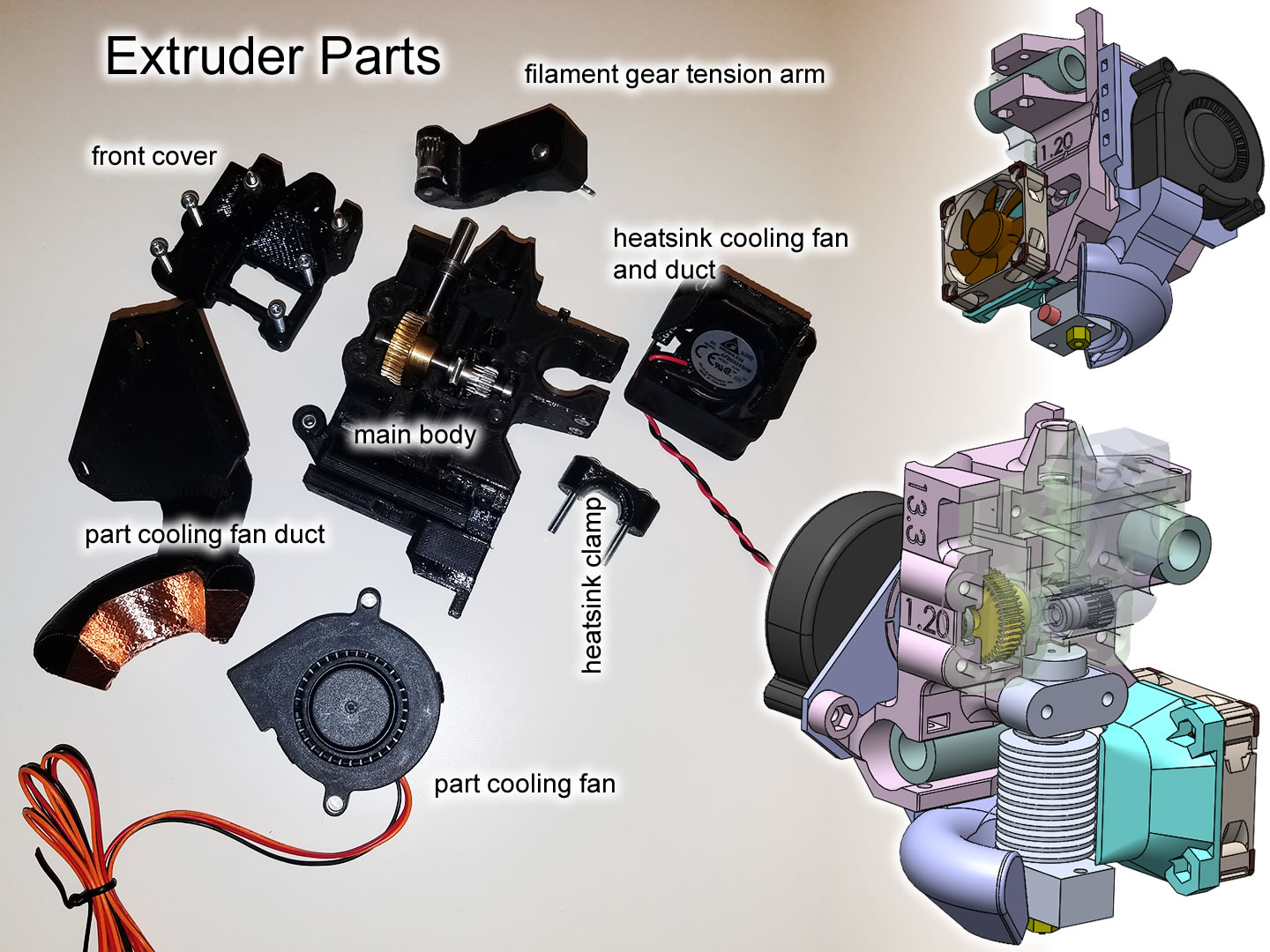
The V1 extruder body design went through many iterations of evolution. The first few were very feature rich and highly integrated, it held a bed level inductive sensor and laser filament sensor, plus the blower fan duct was integrated in one piece, as is the heatsink cooling fan duct. The final iteration does not have any sensors, the blower fan duct is a separate piece that is height adjustable, and the heatsink cooling fan duct is removable.
Justifications for these changes:
- Sensors deemed useless, even Prusa retired their laser filament sensor due to unreliable performance, and as I stated before, the bed level sensor is useless in my design
- The blower fan duct really does need the height adjustment, as I changed the design from a very simple box shape to a torus shape that surrounds the nozzle better, I am not confident that I “aimed” it correctly so I wanted height adjustments
- The heatsink cooling fan surrounded the heatsink too tightly and often broke off when I removed the heatsink. Making it detachable mitigates this risk, plus, it untrapped one of the rods. Now I can remove the entire extruder body from the printer without removing any rods from the printer
Pictures of assembly and installation:
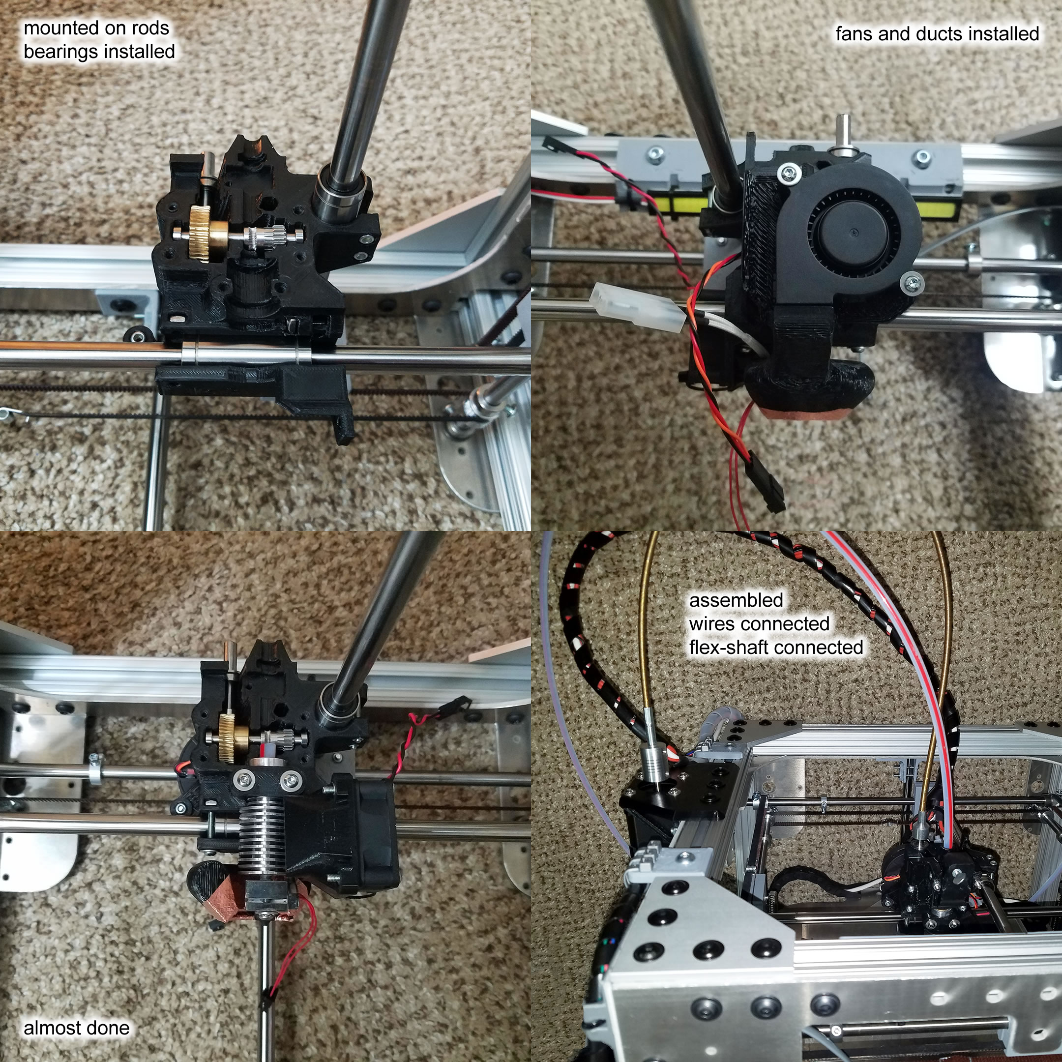
Retirement of V1 Extruder
An issue with vibration was discovered with the V1 extruder. As one of the attempts to fix this problem, more extruder bodies were 3D printed with more distances between the axis linear bearings. This was to hopefully tighten up clearances inside the bearings and act as a preload. The V1 design had many places where hexagonal nuts were embedded deep into the plastic body, which was difficult and annoying to do, plus, they often lost grip internally when the screws were tightened or loosened. Each print took essentially an entire day so I got sick and tired of this design.
The V2 design uses square nuts inserted from the side, much less likely to fail during assembly and disassembly. The biggest screws will screw into the heatsink anyways, which has thread tapped holes, not nuts.
The V2 design started off with slightly tighter bearing spacing too, and the bearing placement is a bit better with respect to the two axis being aligned, and with respect to the center of gravity.
The V1 design had to be assembled while it was installed in the printer, because some parts block the linear rods from going in. It is kind of awkward to put in screws while the whole extruder is in a tight space already. The V2 design can be completely assembled on a desk first, and then mounted on the linear rods as the last step.
Extruder Hot-End
I am using the E3D V6 system, 2.85mm version, but with some premium features and modifications.
The temperature sensor is a PT100 sensor. The heater cartridge is 24V 65W. The heatsink fan is a Noctua 40mm x 20mm, and runs on 12V. The part cooling fan is a centripetal blower style fan blowing into a 3D printed air duct.
I paid some extra money to get the copper heat block instead of aluminum, it takes longer to heat up but has higher heat capacity. Since the bed is the bottleneck of the warmup duration, this isn’t seen as a problem.
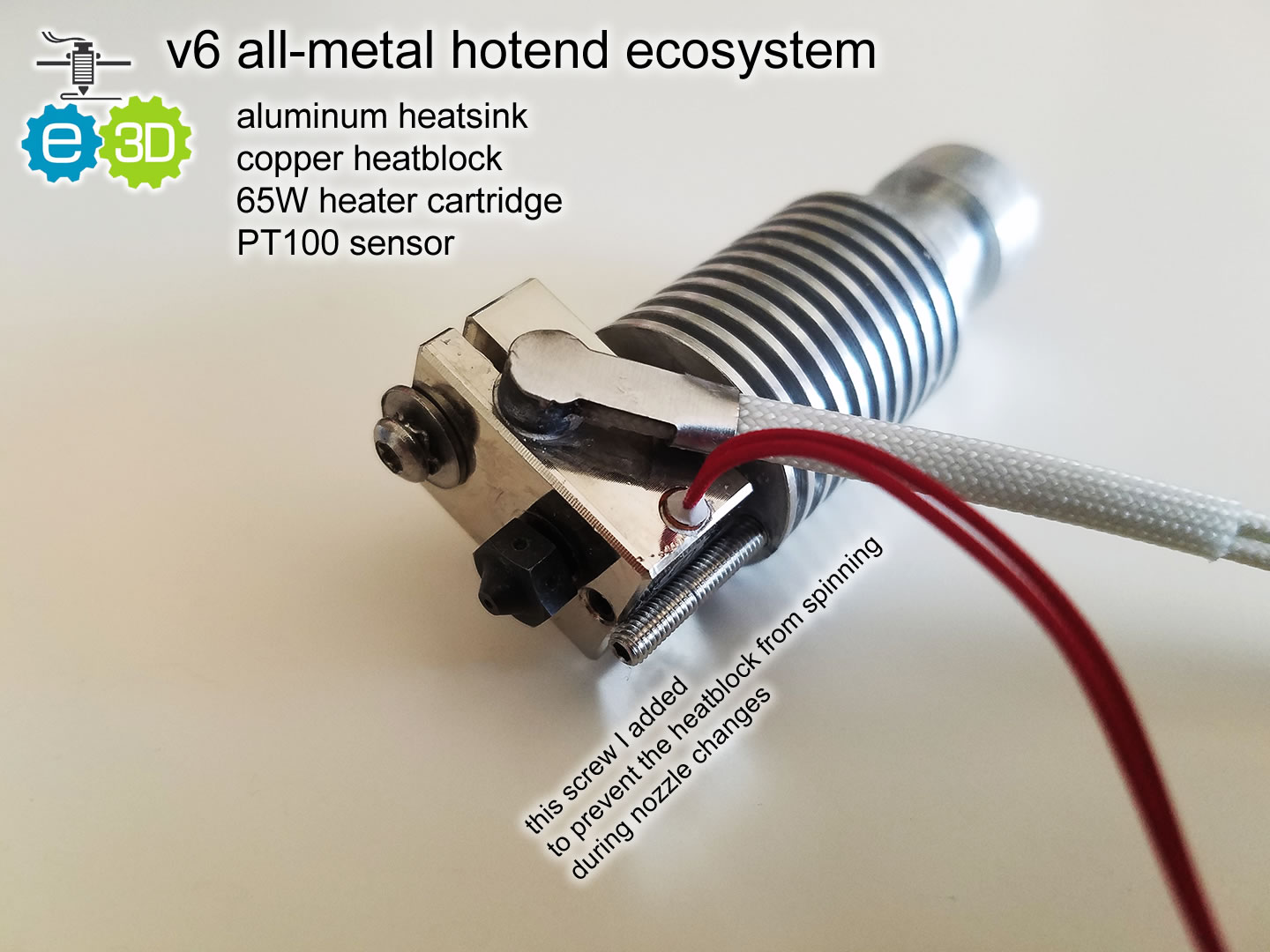
(picture is of the heatsink used in the V1 extruder, the V2 extruder uses the same components except with a Titan Aero heatsink instead)
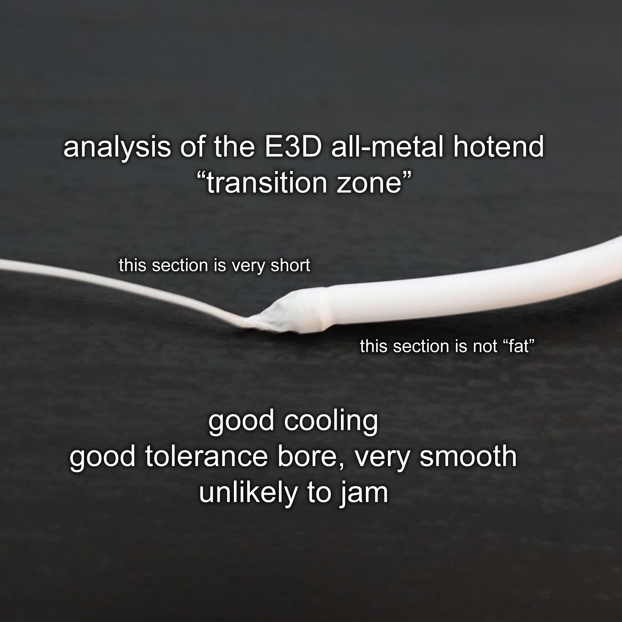
As for how good the “transition zone” of the hotend is, here’s a picture below:
Nozzles
The nozzles are not E3D branded, instead, I am using Matchless Race nozzles from 3D Solex (but purchased from The gr5 Store). This brand of nozzles have multiple internal filament paths so the filament is more evenly heated quickly.
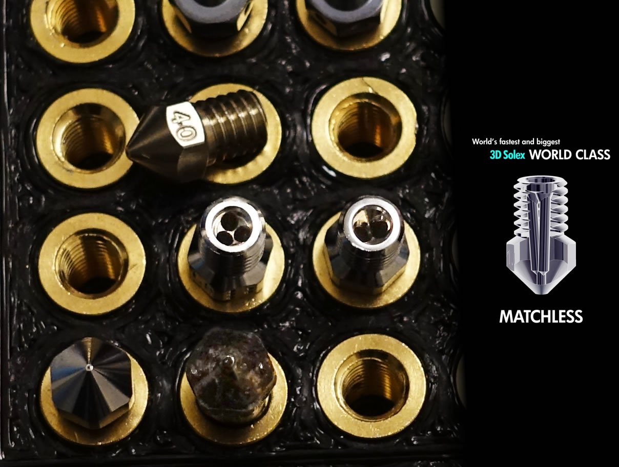
This eliminates the need for a “volcano” heatblock when I use larger nozzle diameters, as they depend on an extra length so that the heat has time to penetrate. With these differences in mind, it is obvious that the Matchless Race nozzles also have advantages in regards to oozing and filament swapping. One key disadvantage is that the multiple paths are difficult to clean, however, I have never had any of my Matchless Race nozzles jam (probably due to the insane torque of the Flex3Drive).
Of course I also own hardened steel and some nozzles with non-stick coatings, too.
One Handed Nozzle Swapping
The Ultimaker 2 Olsson/Anders heatblock or Matchless heatblock allowed people to change nozzles with only one tool. I wanted the same convenience with my new printer.
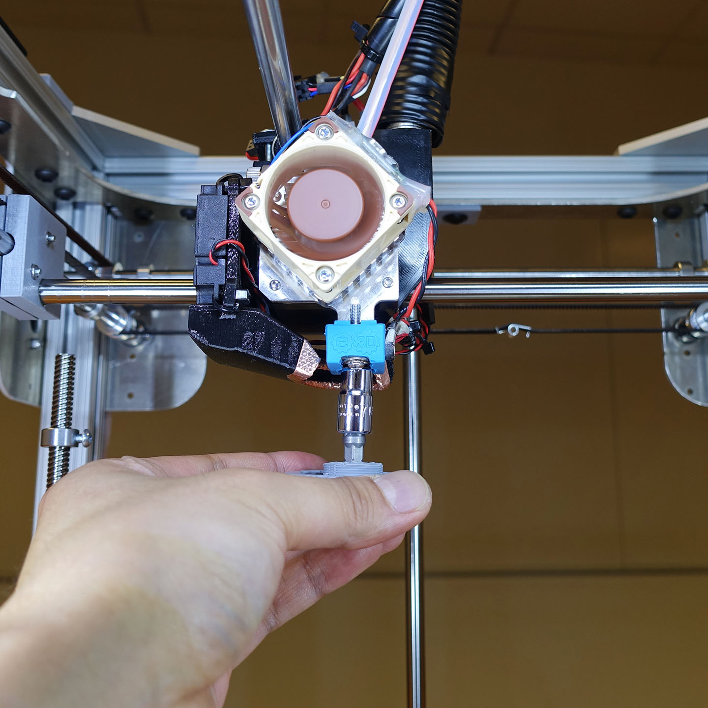
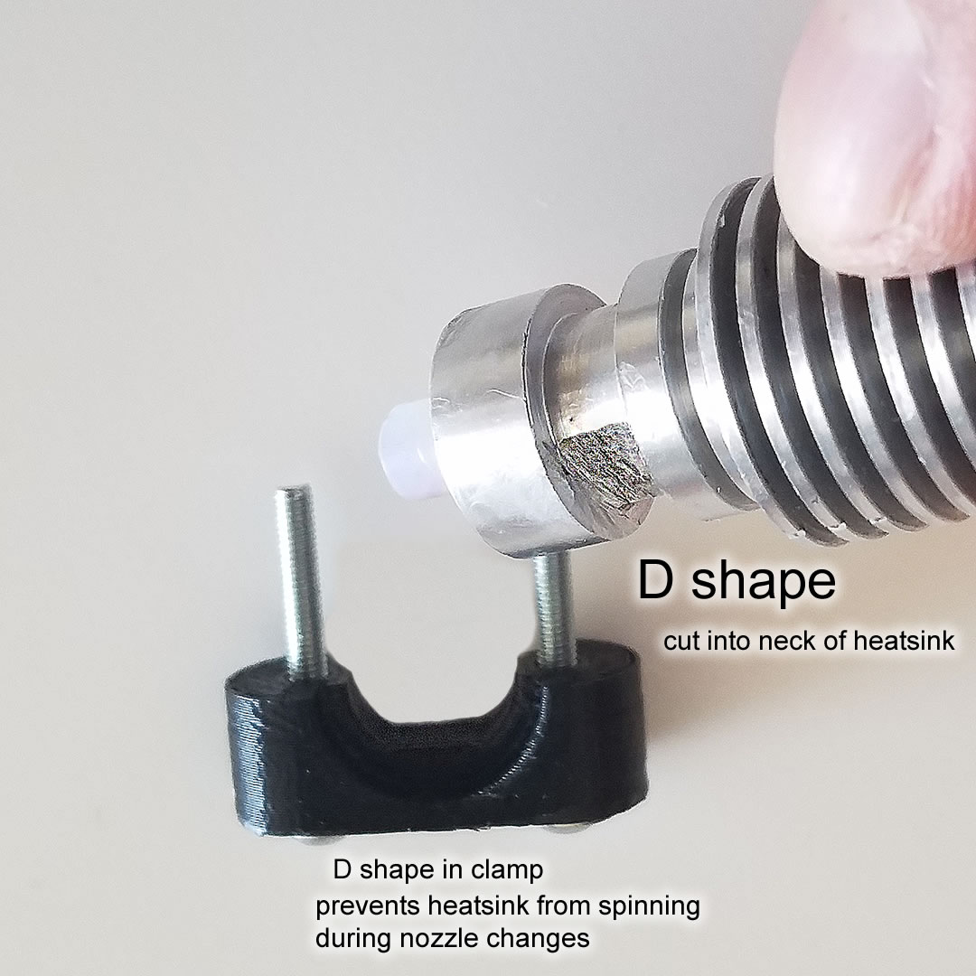
The E3D heatblocks kind of requires two hands to perform nozzle changes, because nothing holds the heatblock still, and the heatsink is mounted with a cylindrical neck (groove mount), plus, the heatbreak is simply delicate (people complain about the 1.75mm version, I am unsure how delicate the 2.85mm version is).
On the V2 extruder, the M3 screw that is usually used to tighten the heater cartridge is now extra long. I cut a tiny notch into the Titan Aero heatsink so that the screw rests within the notch.
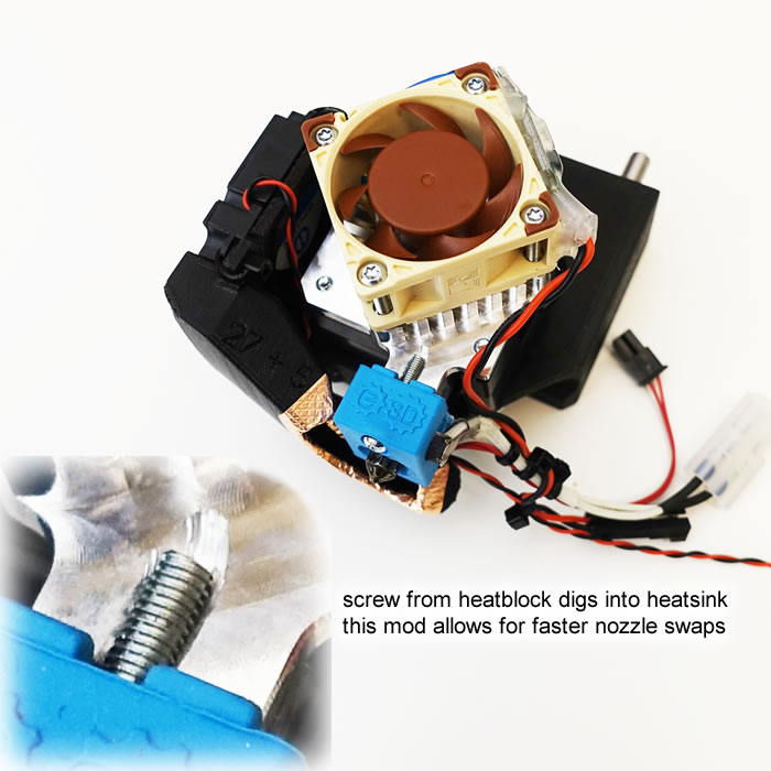
To accomplish this with the V1 extruder, I drilled a hole through the E3D heatsink and put a long screw through it, protruding from the bottom, in a position that locks the heatblock in place. The heatsink’s mounting groove was originally round, so I used a die grinder to grind in a flat section and designed my mount to mate with it.
The heatblock and heatsink won’t rotate when swap nozzles. I do not need a second wrench to hold the heatblock still while I rotate the nozzle with a hex socket.
There’s way less chance of me damaging the critical heater cartridge and sensor wiring during a nozzle swap, avoiding another fire hazard.
Yes, there’s slightly more heat transfer because of this screw I added, but it’s not significant enough to make a difference. I have not experienced any jamming due to heat-creep, and I may never, because my extruder has insane torque from the worm gear.
Filament Pulley/Drive Gear
V1 of the extruder used the Bondtech Mini hobbed gears used in the Prusa i3 MK3. It’s great because it is two gears that rotate with each other and grip the filament from both sides. It’s designed for 1.75mm filament but still worked for 2.85mm filament. The V1 extruder design did not use spring tensioning on these gears, but relied on brute force for grip. This is how Bondtech and Flex3Drive designs their systems as well.
V2 of the extruder used the E3D Hobb Goblin, mainly because it is similar in size to the original hobb gear inside the Titan Aero. It has the same diameter as the Bondtech Minis but has sharper and deeper teeth. It grips better than the Bondtech Minis despite only using a spring tension lever with a simple bearing to apply pressure from the other side. Overall I think this is a great choice for 2.85mm filaments even though E3D doesn’t explicitly say so.
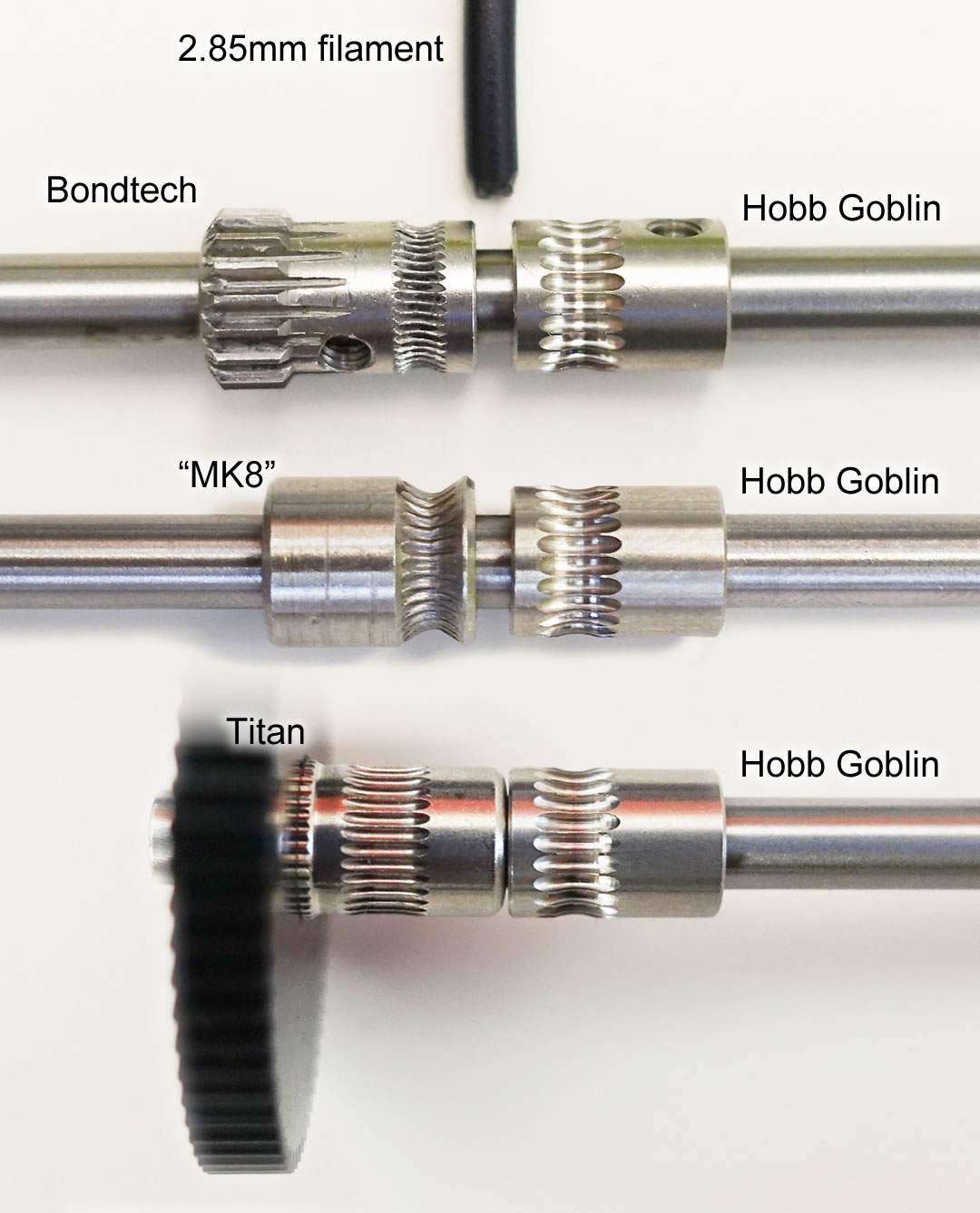
The Bondtech Minis were too wide for the Titan Aero, too much additional work would’ve been required to modify both the gears and the tension lever to fit the Bondtech Minis into the Titan Aero design.
I did consider getting a bunch of cheap MK7 or MK8 gears but reviews all over the internet suggests that quality control is a problem. Bad tolerances can result in uneven extrusion. The Hobb Goblin is essentially a high quality name brand replacement that guarantees good prints, and wasn’t too expensive, so I went with it.
The effective diameter of the Bondtech gear and the Hobb Goblin are both about 7.3 mm, you can use this value to calculate the extruder steps/mm in your configuration.
Safety
There is an emergency stop button on the user control panel. It is wired directly to the Duet’s reset signal. It will halt the printer movements immediately (instead of clearing the command buffer) and stop the heaters as well.
Mechanical Hazards
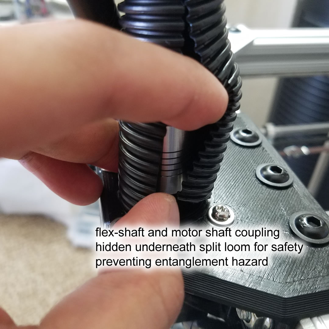
The flexible shaft is a spinning hazard, it might pull somebody’s long hair if it is exposed. It is covered with a split loom to avoid anything getting tangled.
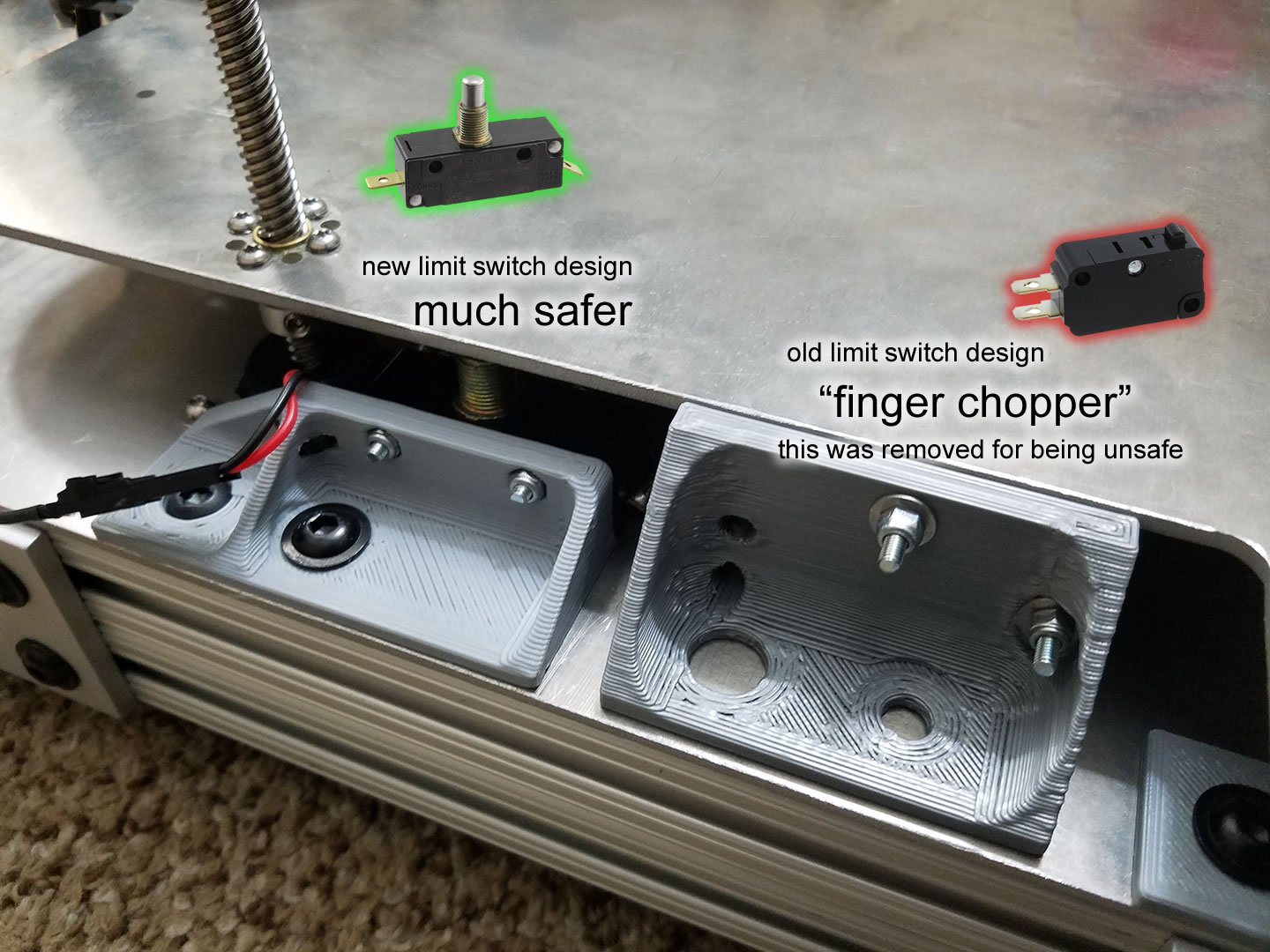
The area under the bed is a crush hazard, but then, all printers of this style have this problem. There’s some room underneath it, and calculations says that the stepper motors will only exert about 30kgf of force if used at maximum settings (which it never needs to). The first design of the limit switch holder was a potential cut/pinch hazard but I redesigned it to be less hazardous.
The gantry components are not as well hidden as the ones on the Ultimaker, but the system is belt driven and there are limits to the motion. Pinch hazard wouldn’t be powerful enough to break any bones and hair tangle hazard wouldn’t be continuous.
Electrical Hazards
I am not using 120VAC to heat the bed, touching 24V is not hazardous.
The whole frame is grounded, I verified that even the rods and the stepper motor casings are grounded. There are actually pieces of copper tape hidden under some of the plastic components that connect parts that need grounding. The DC negative terminal of the PSU is directly grounded too.
Fuses are used on both the AC and DC power rails. (explained previously)
All the wires are protected physically by looms and drag chains to avoid accidental damage. Extra protection is added where a wire meets a sharp metal edge. The entire bottom of the printer is covered by an aluminum panel.
Fire Hazards
All wiring is done properly, all the connectors are rated with high safety factor, and I’ve excessively used silicone insulated (high temperature resistant) wiring.
It’s pretty easy to avoid a fire hazard printer like the Anet. The Anet earned their reputation as a fire hazard because of a few connectors that were not rated high enough for carrying electrical current used by the heated bed.
Thermal Runaway Scenarios
The hot-end can survive a runaway scenario without endangering anything if the 24V fan is on. If the 24V heatsink fan also fails in a runaway scenario, the plastic around the heatsink groove mount might get soft but still hold. If somehow that hold is compromised, then the hot-end will dangle by the heater cartridge wires. If those wires break, then the heating will stop, although then the hot-end might fall and hit something (hopefully not paper)
If the bed heater is in a runaway scenario, the bed doesn’t get hot enough to ignite anything, not even paper. If the adhesive releases the heater pad, it might fall on debris, but it wouldn’t ignite.
Thermal Testing
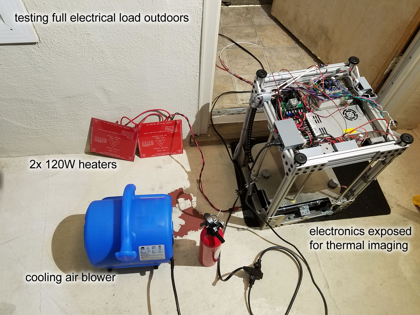
I did run fully loaded tests while using a thermal imaging camera in order to spot unexpected hotspots. During this test, all the circuitry and connectors were exposed so that I can see them with the thermal imaging camera. The bed heater is actually two PCB heaters that are 120W each wired in parallel, totalling 240W, which is 40W more than the heater actually installed in the printer.
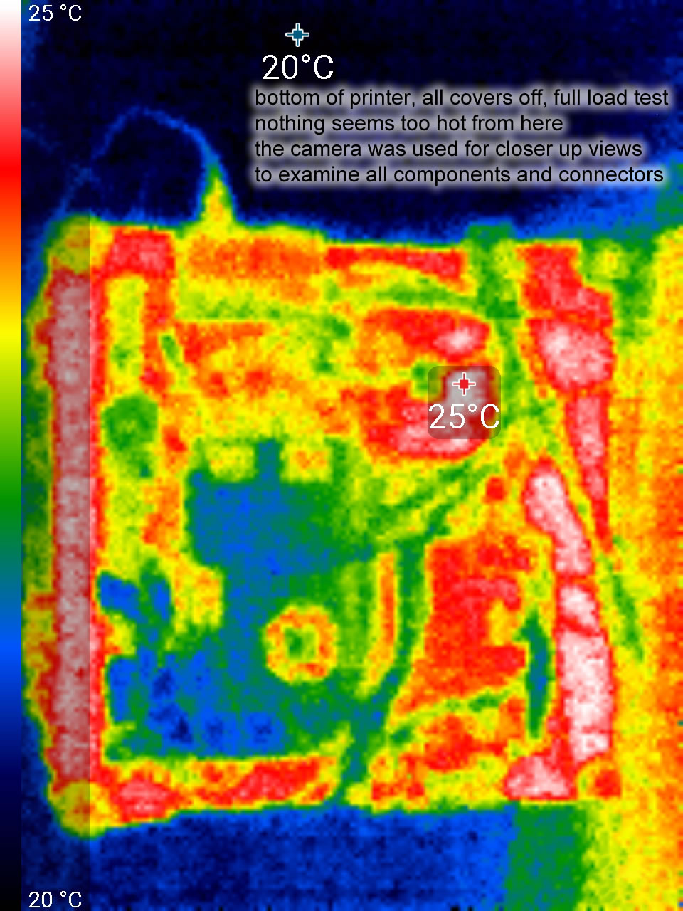
The hottest electrical component was actually the 15A main fuse, which may have had a hotspot, so I replaced the fuse holder. None of the connectors got hot.
Mistakes
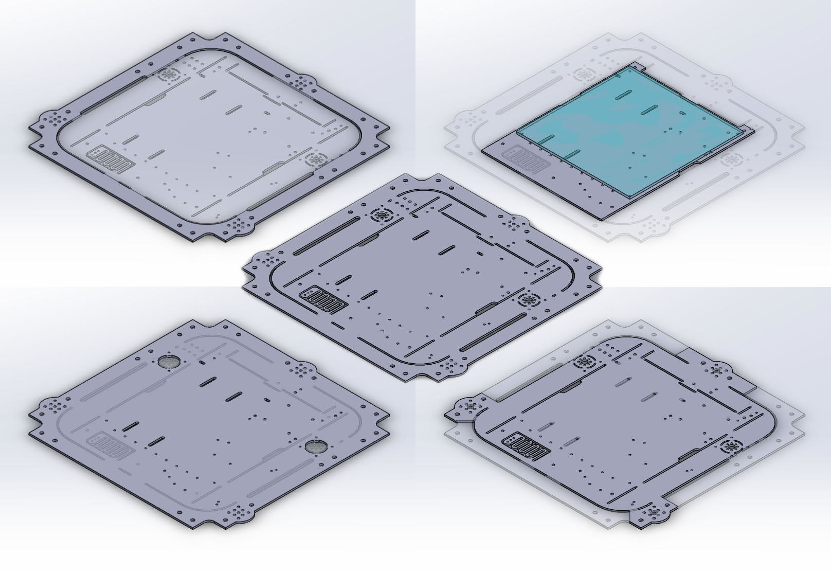
Misunderstanding how waterjet cutting works
My printer design has 4x side panels, 1x bottom panel, 1x top panel, 1x Z axis platform, and 1x heated bed that sits on top.
The bottom panel has a lot of holes to hold all the circuit boards underneath, the stepper motors, and the Z axis rods. Actually, it has more holes than it will ever need because I’ve designed it so I have choices, a Duet WiFi or a Einsy Rambo, a MOSFET driver or two SSRs. The top panel has a giant opening but otherwise matches the bottom panel where the Z axis rods need to be anchored. The Z platform is mostly the shape of that opening, but with larger holes where the rods go so the rods can slide, holes for the leadscrew lead-nut, plus it has holes for the bed springs and drag chain. The heated bed plate itself has holes in the same positions for the bed springs, plus some holes to help keep the glass plate still.
There’s a setup cost for each different design to be cut. So my brain says “what if I made one design that is all of the designs super-imposed on each other? I’ll add some cutout lines with small tabs that I can cut with hand tools later. I’ll save money on the setup cost!”
I went to the effort of using one CAD model for the bottom/top/Z/bed panels, and while in the CAD assembly, they had different configurations so they still looked correct. In a final configuration, all the cutouts/holes are enabled, and the drawing is exported to DXF, sent to the waterjet cutter.
It turns out, setup is cheap, aluminum is cheap. Sand is expensive. I use waterjet cutting for a lot of projects, but I never realized: the sandy abrasives in the water does not get reclaimed! In hindsight, I should’ve realized this would be a difficult thing to do, as being able to reclaim the sand requires being able to separate sand from metal debris during the recycling.
It was a total shock to me when getting a quote for getting my design cut. In the end, it was MUCH cheaper to just get each piece separately done. There are less ugly unnecessary holes everywhere. The bad news is that the CAD model is still a single model with multiple configurations, it’s now more difficult to manage for no reason.
Too many backup plans and leftover design artifacts
See these round bulges on these aluminum plates? They are there on the bottom and top plates because I could choose a round shaped shaft support. I never ended up using one like that. But the shape carried over to the Z platform plate too, because of the “one CAD model to rule them all” mistake I talked about earlier.
Well… that round bulge stops me from enclosing the printer easily with a single panel, such a panel would need to have a bulge, or be placed further out. I also cannot mount any more beams directly onto the existing main beams without a spacer so the new beam clears that bulge.
The other mistake is, on the Z platform, the area under front corner rod bearing, has this long shape meant to allow me to choose a different linear bearing holder. This is so close to the front pillars of the frame that it makes mounting the LED bars difficult.
Incomplete watchdog circuit for the MOSFET driver
I talked about how I made a circuit board for driving much higher rated MOSFETs, and how it had a physical relay that cuts power when a watchdog timer triggers. That safety feature was not implemented correctly so it’s currently not functional, the relay is bypassed.
The idea is, a dedicated microcontroller monitors the communication between Duet WiFi and PanelDue, it will intercept the temperature reports from Duet WiFi and check against temperature limits. There’s a watchdog IC that controls the relay, if the watchdog IC does not receive an edge, it will de-energize the relay coil. Ideally, this handles:
- All sorts of firmware crashes
- Temperature sensor failure, shorts, cut, disconnected, etc
- Dangerous temperatures, such as caused by a failed stuck-on MOSFET
(it can’t handle a loose sensor, one that works but is detached from the surface it needs to monitor, but Duet’s firmware handles that type of failure)
The problem is that the watchdog IC only kills the relay for a few milliseconds and then turns it back on. Why I didn’t realize this? I didn’t understand how the watchdog IC behaved because I misread the datasheet.
This circuit board was really expensive to build. Hence why I am declining the rebuild it. I’d also prefer not to rework it with a patch job.
I am not terribly worried. While it is a fire prevention feature, I have confidence that I don’t need this particular feature. Please see the other section I wrote on fire safety.
Plus, I have a thermal imaging camera so I can catch hotspots during initial testing.
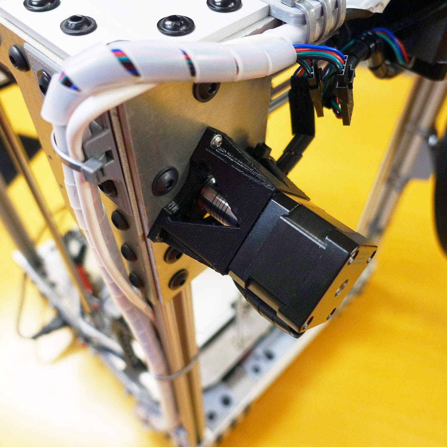
Extruder Motor Gearbox Assembly
The worm gear reduction inside the extruder has a 40x reduction. From my calculations, this would be a bit slow to print at high speeds (target is 80mm/s) with larger nozzles (such as 2.0mm wide). So a whole gearbox was designed to give the stepper motor a 5x speed boost before it drives the flex shaft, so the final ratio is actually a 8x.
This was accomplished by purchasing a smaller stepper motor (NEMA 11) with an attached planetary gearbox, removing the casing from the smaller stepper motor so that there’s no magnetic drag between the permanent magnets and the windings and stator, and then attaching a bigger NEMA 17 to the gearbox’s output shaft. The smaller stepper motor’s shaft is extended, which is now the new output shaft.
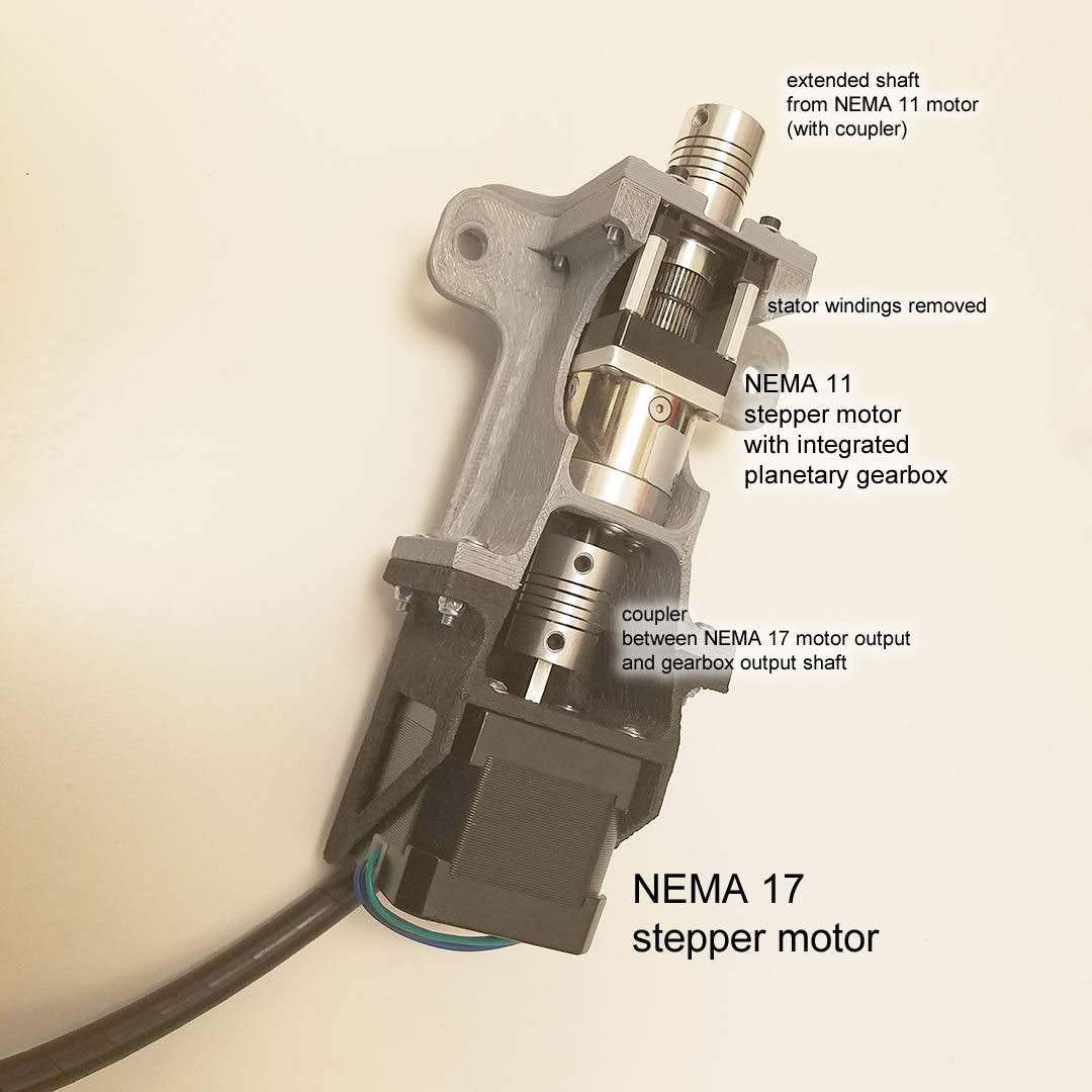
While testing, it was determined that the torque of the motor isn’t enough to reliably drive the entire extrusion system. This module was removed from the printer and a non-geared NEMA 17 motor is mounted instead.
Heatsink Cooling Fan on Extruder V1
The original design used a 24V heatsink cooling fan, and it had two problems: it was too loud! and it was too powerful. The fan duct design didn’t really close off the air path downwards, so a lot of air was going down to where the nozzle is. This makes the fan act like a part cooling fan, but sometimes you don’t want to cool your part.
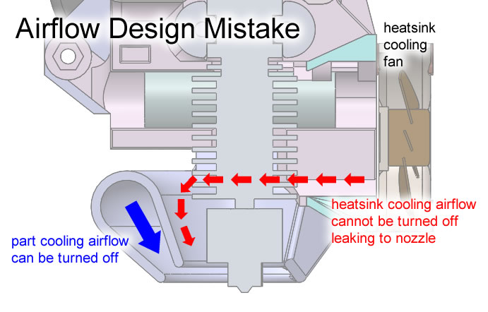
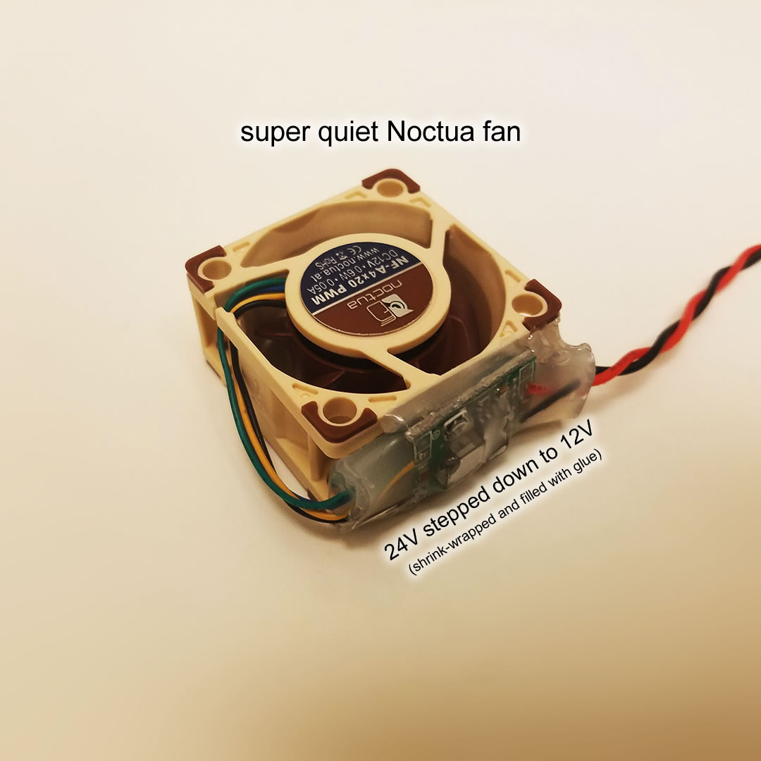
The solution was simply use a Noctua 12V fan instead. I added a DC step-down converter to convert 24V to 12V, and attached that to the new Noctua fan. There is still plenty of air flow to cool the heatsink, but a lot less noise and a lot less leakage downwards.
With the V2 extruder does not have this problem because of the Titan Aero’s heatsink design, which forces the air sideways only, and has the fan mounted tightly against all the heatsink fins.
Possible Improvements to Emergency Stop Button
First, it is always better to put the emergency stop button directly on the power supply line. I could do that, but it’ll involve wiring up really thick wires to the top of the printer, and the button will be much bigger. This will look too ugly.
The other possible improvement is to use a NC switch instead of NO, this would mean the system could detect if the wire for the button is cut by accident (since cutting the wire would appear as a button being pressed). The risk of this happening with my setup is extremely low as the wire is hidden inside the T-slots of the frame beams.
Think about how many 3D printers are currently out there without a E-stop button at all. Basically none. So I am pretty happy with my implementation right now.
Other Topics
Filament Size
I choose to use 2.85mm filament. It has many objective advantages over 1.75mm filament, and I also use the same filament for my Ultimaker 2 and 3.
The biggest advantage of a thicker filament, for me, is the speed bonus. Since more plastic is extruded per step of the motor, the theoretical maximum speed is higher. This is obviously important to me since I am using a 40x gear reduction.
Some people claim that 1.75mm filament can print faster because heat can transfer easier to the middle of a thinner filament. But I am using Matchless Race nozzles, which splits the 2.85mm filament into two or three smaller (less than 1mm) tubes so it gets heated much better than just one straight 1.75mm tube.
The E3D heat-break for the 2.85mm filament is obviously stronger than the 1.75mm version, less likely to snap.
Thicker filament is stiffer. This means faster and more reliable usage of softer materials, because the filament will not buckle as much in any of the tubing. This is important to me to prevent jams during filament loading. The other advantage of less buckling
Systems designed for thicker filaments are generally more capable of handling poor tolerance and dirty filament. Of course, all the orifices are made a bit larger than the filament itself, but the over-sizing is more dramatic for 2.85mm than for 1.75mm. This does translate into less jamming from bad filament.
Speaking of bad filament, another advantage is that there are simply less no-name filament dealers that sell low quality filament for unbelievably low prices.
For my heavy engineering focused usage of my 3D printers, I have not seen any shortage of the specialty filaments I like in the 2.85mm size format.
Printing with 1.75mm filament in theory should be have more precise extrusion volume if the system was an ungeared direct extruder. But I am using a geared down extruder which adds precision.
One huge disadvantage of 2.85mm is the lack of a off-the-shelf automatic multi-filament changing system. But I have toyed around with redesigning the Prusa MMU 2.0 to fit 2.85mm instead of 1.75mm. Technically all the components already fit, except the tubing.
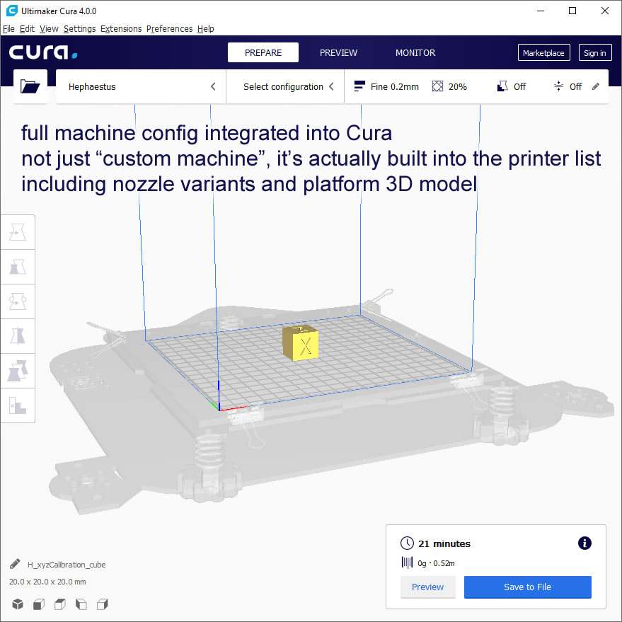
Cura Profile
I made a whole printer definition file for my printer. This means I can click “add printer”, and select “Haphaestus” directly instead of “custom”, and it will always have the correct settings for Haphaestus. I’ve also gone the extra mile, there are several machine variants to define the nozzles I like to use, and even the 3D model of the platform is available. The definition file also allows some light Python scripting so layer heights and line widths are calculated from the nozzle size.
LED Lighting
The lighting of the Ultimaker 2 actually matters a lot! It looks absolutely beautiful, it makes the prints look beautiful inside, it’s great for taking pictures/videos and it makes it easier to see what’s going on while it prints.
I wanted to add some 12V lighting that can be adjusted. I did not want to use PWM to adjust the brightness because it results in flickering when you use a camera. That meant I wanted a adjustable constant current power supply to drive the LEDs instead. But I got lazy. I know these LEDs actually operated between 9V and 12V, so I didn’t really need adjustable constant current, just adjustable voltage.
I purchased an appropriate DC/DC step-down converter that converted 24V down to about 12V. The potentiometer on it was removed. By experimentation, I discovered 1 kiloohm on the potentiometer roughly equated to 1 volt. (the resistances I use later are only rough values, not the true values)
The first idea would’ve been to wire a 9K resistor and a 3K potentiometer in series, but this was not a good idea. If there was an open circuit (such as a connector coming loose, or a wire breaking), then 24V would shoot into my LEDs rated for only 12V. I do need a connector because I haven’t planned out all my control panels and wiring yet, so the risks are very real. The next solution to this is still simple, use a 9K resistor and 3K resistor in series, soldered directly to the converter so there’s no risk of breaking, then wiring a 1M potentiometer in parallel with the 3K resistor (using a connector first). Great, this works, but the adjustment isn’t very linear. To make the adjustment slightly more linear, use a logarithmic potentiometer.
Accessories
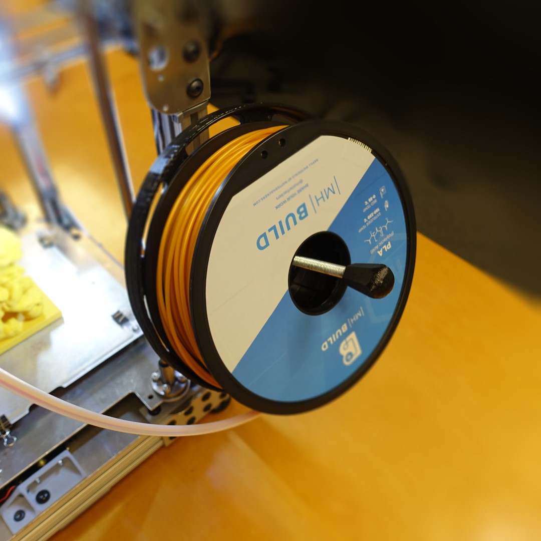
Spool Holder
The plate captures filament that falls off the spool, preventing tangles.
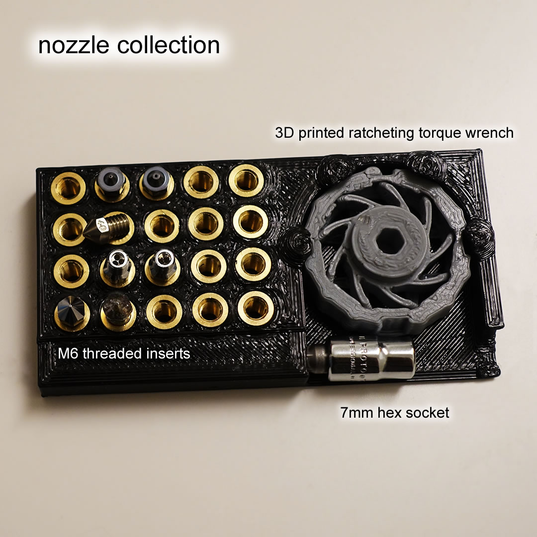
Nozzle Collection
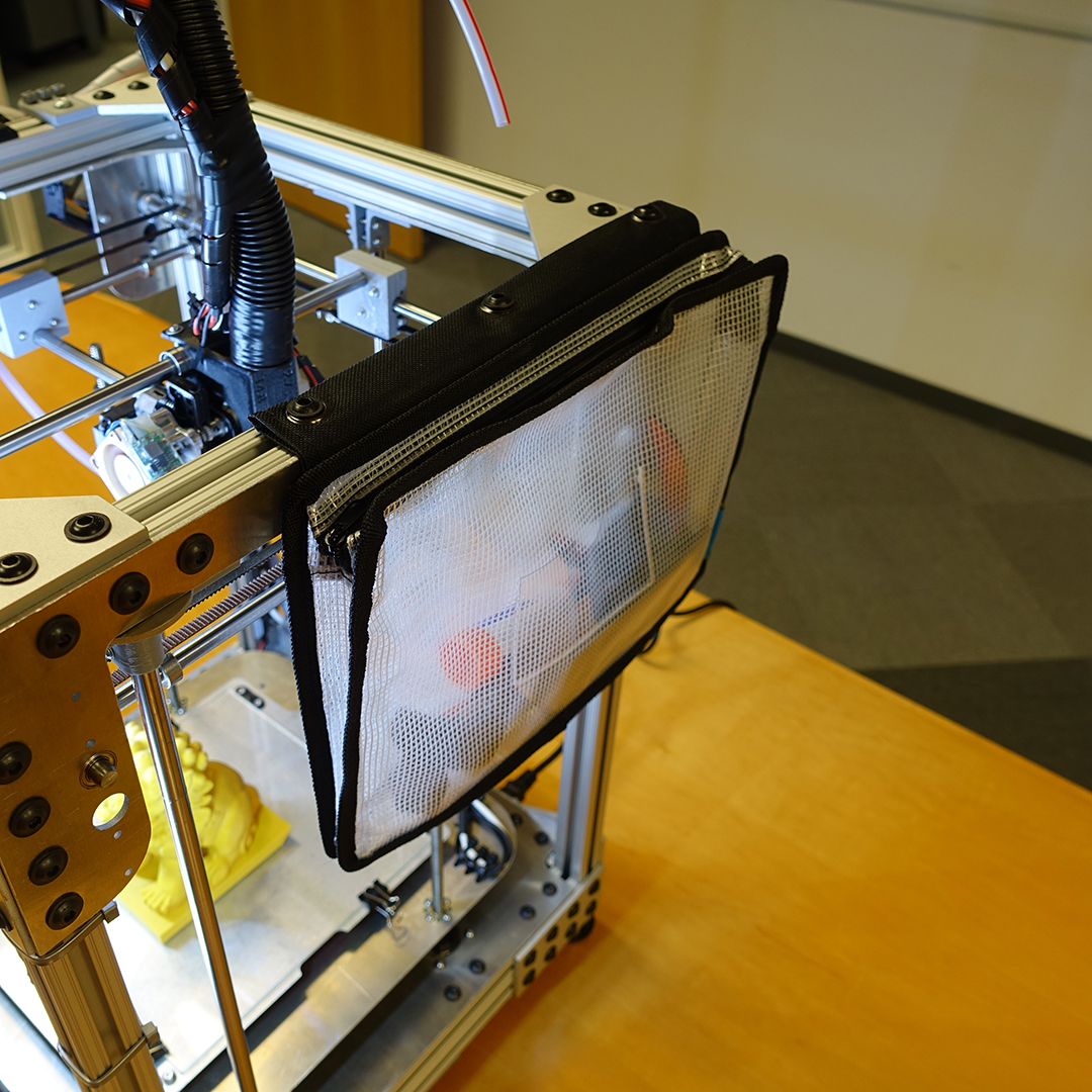
Accessories Bag
Glue sticks, putty knife, and nozzles go in here:
Failure Recovery (somewhat related to stall detection)
Adding the layer-shift-recovery feature would be a firmware feature that I can play with another time, it’s not a must-have. The Prusa’s power outage detection feature works differently from the one featured on the Duet. The Duet detects voltage drops from the 24V power rail, while the Prusa uses an opto-isolated zero-cross detector on the 120V AC power input. In theory the Prusa would be able to detect a power outage sooner, and thus have more time to respond by moving the nozzle out of the way of the print. My design has a bed that moves downwards, so during a power loss event, gravity assists the bed moving downwards, thus requiring less power. If my implementation doesn’t work then I am considering trying to implement the detection on the AC side, but using a contactless capacitive coupling detection circuit instead of using opto-isolation. Power loss recovery is not really a must-have feature for me either, so no effort has been put towards additional experimentation here.
Duet 2 WiFi Review
This is probably the best controller circuit on the market right now if you are trying to build a 3D printer.
My printer is soooo quiet! The loudest part is actually the cooling fan of my power supply, which isn’t even always on. The motors do not make a sound due to the Trinamic stepper motor drivers on the Duet.
I love the way Duet uses gcode macros for you to add configurations and additional functionality. Since I can simply use the web interface to edit the code and test instantly, it is really convenient. I am sure it allowed me to add functions to the firmware that would’ve taken forever if I tried to do the same thing on Marlin or Smoothieware.
The Duet3D support forum is really active too. Help is always prompt, and they are very responsive to real problems that require RMA’ing a board.
The web interface is amazing. The PanelDue interface could use some more work but it is still enough to make the printer work completely offline if needed.
The documentation is excellent, I am constantly on their gcode reference page and I have a laminated printout of their wiring diagram while I did my wiring.
But be warned, I do feel that the Duet is unsuitable for usage by untrained individuals. There are still edge cases I encounter where the temperature doesn’t get set correctly or otherwise, when I have to manually input a value somewhere. The firmware interaction between the PanelDue and the Duet also has some annoying UX bugs in certain edge cases.
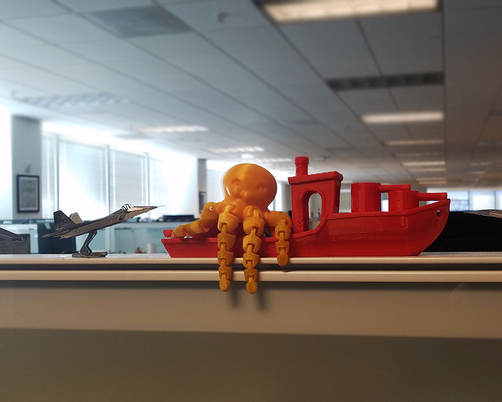
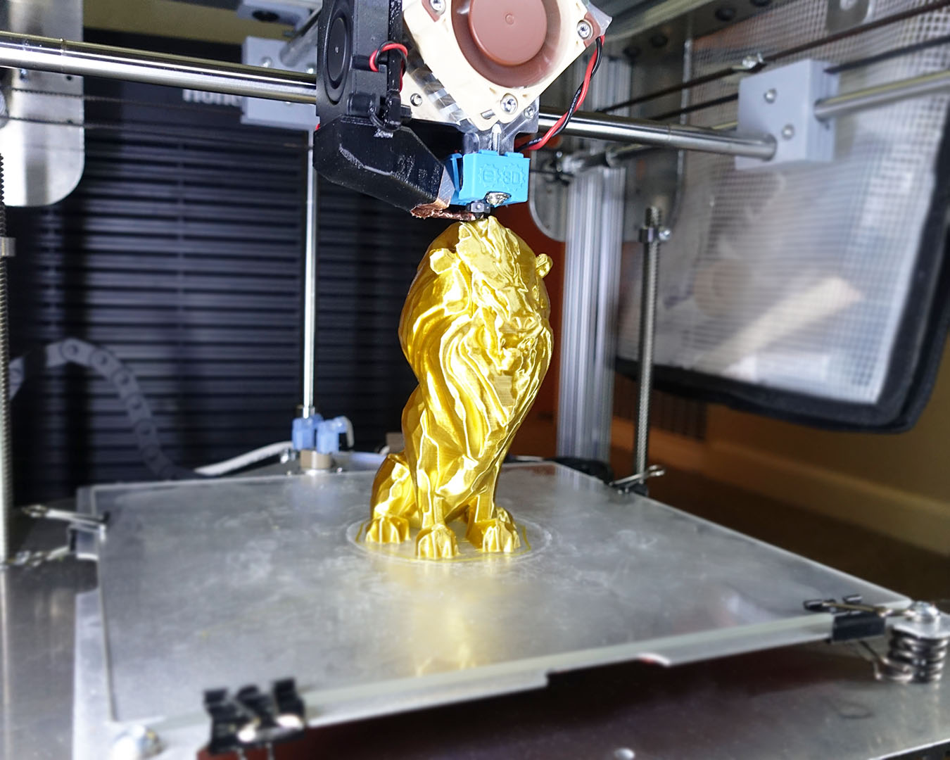
More Pictures
This is a pretty incredible project. I’ve toyed around with the thought of building my own 3d printer and from your post it looks just as involved, if not more so, than I had figured. Amazing work!
A 3D printer is really a great invention as you can print any object out with this printer. It has made human work much faster and easier.