I made a breakout board for the STM32F405RGT from ST.
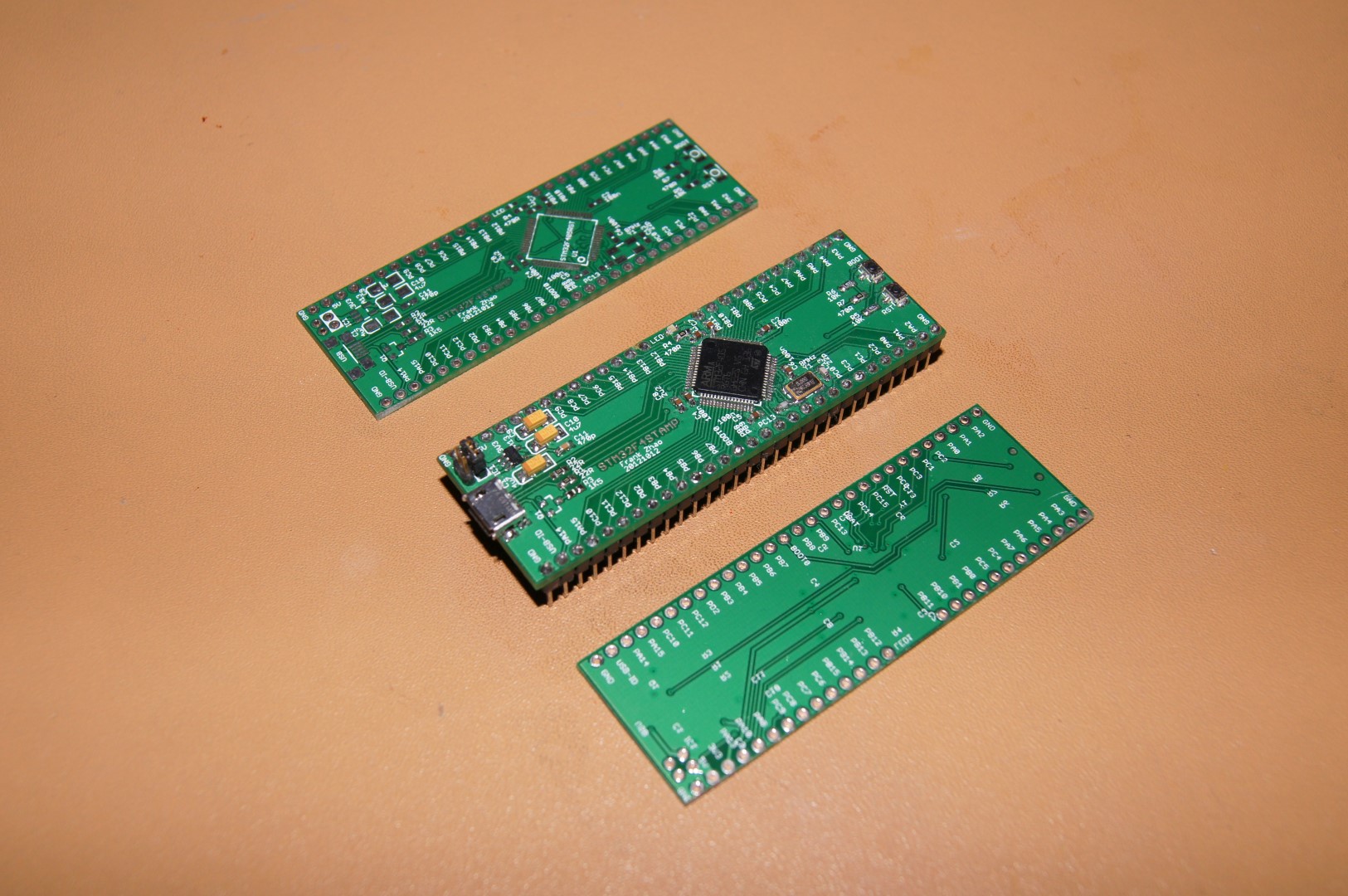
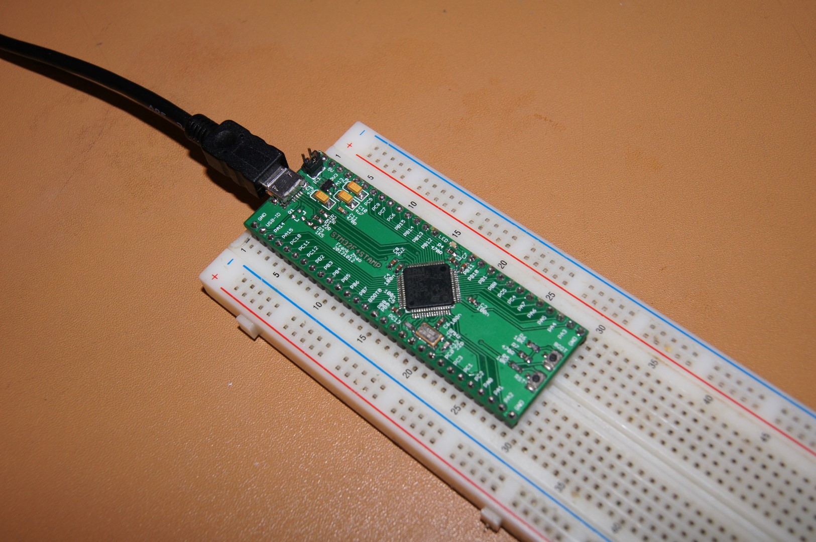
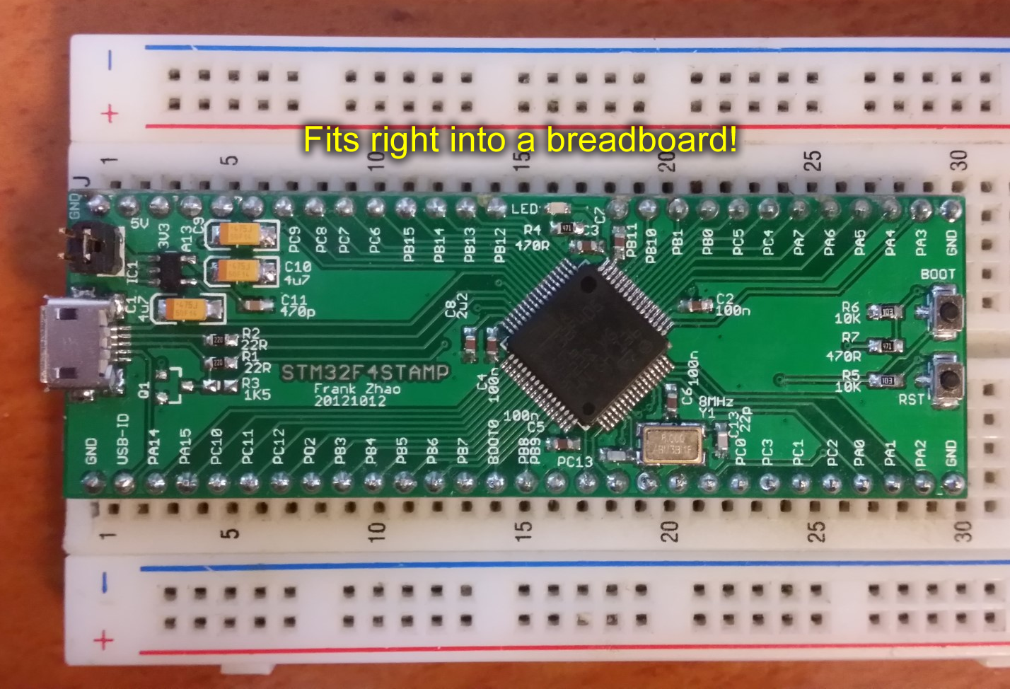
I really like the STM32 family of ARM microcontrollers. This breakout board is a narrow design that fits perfectly on a breadboard. Every pin is accessible. It has USB, a reset button, and a bootload button. The chip itself has a permanent USB bootloader that is activated by the bootload button. This means that no equipment is required to program this microcontroller, no expensive debugger, nothing at all except a USB cable.
If you are interested in the design, click here to download the EAGLE files (version 20131027) including part list. If you have received a PCB from me, please check your version number. Other versions are on the bottom of this page.
Bootloader
I will assume you know how to compile a program for STM32F4 already. You should have either a *.hex or *.bin file.
First, read ST’s application note AN2606. Inside, it describes how the bootloader works and how it’s activated. Basically upon reset (or power up), the bootload button is sampled, and if it is pressed, it will enter the bootloader mode. If it is not pressed, then the code that the user previously programmed will run.
ST’s application note AN3156 describes the protocol used in the USB DFU bootloader. You don’t need to read this but it’s interesting.
You need to download a tool called DfuSE Demo (UM0412 and STSW-STM32080), written by ST. This tool will let you program a *.dfu file into the microcontroller, if it is in USB DFU bootloader mode.
To generate a *.dfu file, there’s a “DFU File Manager” program that is included with “Dfuse Demo”.
In conclusion:
- compile your code into *.hex or *.bin
- convert your *.hex or *.bin to *.dfu using DFU File Manager
- activate the bootloader by holding down the bootload button, then resetting or powering on the microcontroller
- run the Dfuse Demo tool to flash the *.dfu file into the microcontroller
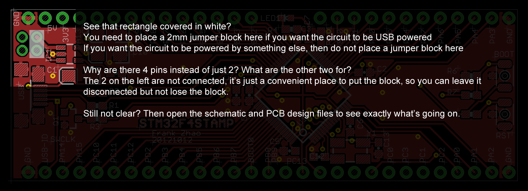
Power Source Jumper
Other stuff I want to mention
You can probably put the .NET Micro Framework on it, it uses the same microcontroller as the Netduino Plus 2. I can put the default Netduino Plus 2 firmware (both the bootloader and CLR) on it and it will work. The networking and SD card slots are missing, but the internals of the .NET Micro Framework is so intertwined that it is not worth the effort to remove those bits of code.
If you have a ST Link or any other SWD debugger, it will work with the breakout board. Then you wouldn’t need the bootloader anymore. The bootloader is permanent so don’t worry about losing the bootloader.
I have a page on my own wiki to help you get started with STM32: STM32 Starter Guide
Giveaways
You might be visiting this page because you’ve obtained some of my spare PCBs. Please pay attention to the version number printed on the PCB.
Version 20121012 is the first ever revision, the files are here (version 20121012, EAGLE schematic, PCB, and part list). It has a minor flaw: Q1, R7, and R3 are not required, in fact, if you installed those three components, it will make the bootloader not work in some situations.
If you are completely new to ARM microcontrollers but still asked me for a PCB, don’t hesitate to ask me for help!
Very nice website, finally someone that inderstand the importance on not always having a white background ;), and very good material.
I have a phone with AMOLED screen so dark backgrounds save battery, I’m being environmentally friendly.
Thanks for the kind words.
This breakout board looks great, just what I’m looking for. But where I live (3rd World) getting parts to populate the board is next to impossible. I would like to see you move to a Rev.2 board then sell them populated or as a board and parts via Tindie or perhaps via Seeed. Let me know if you plan to move forward with this and offer a full kit and/or a pre-built board.
Mate ! But does it plug right into a breadboard ?
you have 29 pins in 30 holes and they all seem offsett somewhat. Better show us a better picture of the lineup huh?
If you must confirm the pin spacing, check the PCB file.
Hi,
very cool project. Till now i only knew about these breakout board for the mcu but a complete eval board for breadboard is great! Love it!!!
Maurice aka mucki
Hello
I think it would be a realy nice idea to put thet on kickstarter or indiegogo 😀
Hello:
I am very like this board,and in my county,we usually used STM32F10X, it is cheaper than 40x,so that’s the reason why i usually use 10X instead of 40X. And is there have any 10X board that i can use?
Thanks
QianFan
From China
It might be pin compatible, you’ll have to check the specific chip yourself
Thanks Frank,
I’ve been interested in getting started with the STM34F4 series for more than a year but just didn’t have the time to learn what I needed. After getting familiar with the C8051F85 and nRF51 systems I am ready to start my first project with the STM32F4 and this site will really help me a lot! Thanks!
I am going to use your EAGLE design as a basis for my own board but I wonder how I could get a pcb from you to try out?
Have you used the smaller UQFN or BGA packages?
Have you integrated sensor onto any of your boards, or blue tooth?
Thanks again for a great place for me to start from.
Kris
Super website Frank and thanks for sharing!! I thought the absolute max ratings for the STM32F405 was 4.0v but in your design the USB power (VBUS), which I assume is 5v goes straight into pin 42 (PA9) on the uProcessor. I assume you didn’t have any problems with that?
I’ve studied many schematics provided by ST that shows their chips used in USB applications. All of them ware wired this way. I’m sure it’s safe to do so if ST’s schematics shows it like that. Plus, the datasheet shows that pin as 5V tolerant. Look in the pin table where the word “FT” means 5V tolerant.
Thanks Frank – you were right (as I knew you would be!). I finally got my bare metal STM32F411 working with the USB connection and able to load the DFU program. I even made the mistake of adding a pull up resistor on USB D+ line until I realised it wasn’t needed – after reading the data sheet and seeing your older design. I got the GNU Arm toolchain and GDB debugger working too (using original STM32 Nucleo). Thanks for your help.
Hello, I am new programming for this chip. When I push the boot button and then plug it in, I can see the board on my computer as a hardware. I did it right. But the problem is “how can I send a program?” For example a blink application. Could you help me?
Thank you in advance
Please read the whole page again and look for Dfuse and the starter guide link.
My microcontroller appears in PC when DFU mode is on(Press and Hold button and power on). And also uploads the dfu file successfully. But after that(Without dfu mode) it doesn’t appear anywhere in PC. Like MFDeploy or Device Manager. What should I do ? Where could be the problem ? The microcontroller is new.
My microcontroller is STM32F205RGT6, is that a problem ?
In your firmware that you’ve uploaded, do you manage to initialize USB as a CDC/Serial device ? Otherwise, it won’t advertise as is …
I do not know about that, I tried with Netduino 2 and Netduino 2 Plus firmwares, noone of them worked.
Do you really wish to use Netduino firmware and C## on the STM32F4Stamp ?
There could be several pitfall such as the networking witch is absent on the Stamp.
You should look at http://stm32duino.com for Arduino look-alike support.
This might be a better choice if you insist on using the Arduino IDE on an STM32 platform:
https://www.tindie.com/products/onehorse/dragonfly-stm32l4-breakout-board/
It will soon be available in production quantities but it’s open-source so you can build your own too.
@Martin : Netduino 2 doesnt have networking, also I already have coded all in C# and netduino. Just need to upload to custom board.
Hi,
is it possible to use the USB connection as supply, booloader and CDC Device to communicate with the PC?
Thanks in advance
@lucky2, if you look at the schematic, there is a jumper to select where the power comes from, so, Yes, the USB can power the board
@Martin, Thanks for your help. Is it also possible to test the DFU Bootloader with a discovery board? I connected Boot0 to Vdd and Boot1 to GND an removed the to jumpers on the ST-Link (CN3), but the DFUse doesn’t recognize the board. Am i missing anything or does it just not work with the discovery board?
I don’t know, it should work.
I have a Disco-F429, but since the is a built-in ST-Link, I’ve never bother trying DFU on this one.
Why are you not using the ST-Link ?
Normally i’m using the ST-Link. Just wanted to try the DFU bootloader, so nothing meaningful just for fun 😉
Maybe you can ask help here http://stm32duino.com …
Hi, i got it working with the Discovery Board. Apparently something went wrong with the driver installiation. Now I have one more question: Does every STM32F405 support the DFU Bootloader if i buy it somewhere or is it completely erased and I have to enable the DFU bootloader first?
Yes ! All STM32F4xx are supporting DFU uploads as well as Serial uploads since this bootloader is located in ROM. You simply needs to apply proper levels to BOOT1/BOOT0 pins and do a reset.
Hello again 🙂
Now i have another problem and would appreciate your help: I created my own PCB an now when I’m trying to get in bootloader mode it doesn’t work. I have a LED connecetd to PB13 and if i press the boot0 bottom and repower the device this LED starts to glow. If i don’t press the bootloader bottom while restarting, the LED doesn’t glow. But nevertheless nothin happens in the DFU program. Is it possible that the µC is defective or is there something else I’m missing?
Is the BOOT1 pulled-down ?
Thanks for your fast reply. Yes, the BOOT1 is pulled to GND with a 10k Resisitor. While I’m pressing the Reset Button the LED stops to glow, so this seems to work, but it won’t go into bootloader mode.
While BOOT0 been HIGH ?
Are you on Windows ? If Yes, you probably need to install a driver.
On Linux, dfu-util is the tool to use.
Yes, when i press the button, BOOT0 is connected to 3,3V. For the Bootloader i did pretty much the same, as in the example.
I’m on WIndows, i already installed a driver for using the Discovery Board, so i think this should be the same?
Then, it must be something else …
No clues other than check again Frank’s schematic.
Hm, I still don’t have any clue. I noticed that the DFU is sensitive about the external Crystal. When I’m in DFU Mode on the Discovery and try to measure the Frequency with the oscilloscop the DFU connection is lost. And in DFU mode PB13 is also on the Discovery Board high, so the switch into Bootmode should work. Any things on the USB connection i may missed? Connected the VBUS to 5V USB and PA12/11 to DP+/DP-. I use a crystal with 16MHz(18pf load capacitance) with two 24pF capacitors and i can’t measure the frequncy at all. Can someone test if they can measure the frequency in DFU Mode on their board? Thanks in advance 🙂
I would rather try to lower the capacitors values, or even better use an external clock source to temporarily figure out the issue.
Hello,
I’ve made up the board from the latest examples and am having trouble getting it to show up in DFU mode. I am currently programming both a Discovery Board and a Netduino using dfutil so I know I have the right tool chain setup. I did continuity checking over the whole board and it matches the schematic exactly. The only part I changed was the oscillator, I used a 8MHz +/-10ppm with a slightly higher capacitance of 18pF. When I connect the jumper 5V is apparent but checking the 3.3V line it only reads 1.2V. The LED is also visibly flickering which my first thought might have been due to the different oscillator. Any suggestion would be greatly appreciated as I would love to get this board up and running.
Thanks!
I am suspecting either a bad LDO or there’s a short somewhere causing excessive current consumption and thus the LDO to fail. Does the LDO get hot at all? Can you get current consumption measurements?
Yeah the LDO gets pretty hot. Current draw is ~300mA which seems very high for a board without any peripherals. I did try swapping out the LDO but no change. I’ll go over the board again and see if I can identify any shorts I might have missed the first time. I went over each individual pin on the chip under a microscope so I’m certain theres no bridging happening there. Thanks for getting back to me so quickly Frank, really appreciate it!
Right again Frank! I soldered up a third LDO and it solved the problem. I can successfully detect the device in boot loader mode. Thank a lot for you help.
Hello Frank Zhao, I am making a development board (only for myself i don t want to sell it) with f103rc/f405rg and while i was scanning the web for similar works i found your page, i like it!
Could I ask you which is the purpose of the usb id wired to PA10?
Thanks
i answer myself: it s needed if you want to use the USB OTG
I have for PCB’s on the way and am just getting my parts together. I am stuck on the tantalum caps C1, C9, C10 the 4.7uF. Can anyone please provide me with a suitable, readily available MPN for them please. Thanks in advance.
I got my board built and running but am still trying to work out how to upload via USB. I am using STM32 Cube-MX and Keil but they do not support USB upload. Looking at Dfuse now as Frank suggested but trying to get dfu output from Keil. Short video here and thanks Frank it was fun to build and start to learn to use. https://www.youtube.com/watch?v=WyKd_PA3HHU
I’m a little late to the party i think, but i thought I’d see if you knew what eagle.lbr you used specifially for stm32 chip