This is the next step in my mission to make my car function 7 years newer and feel like a jet cockpit.
(click here if the above video isn’t loading)
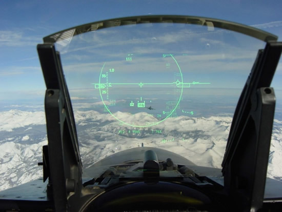
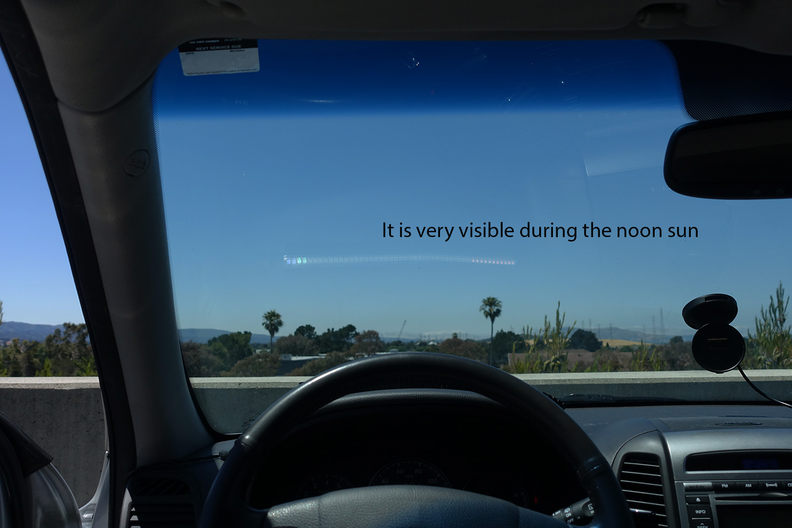
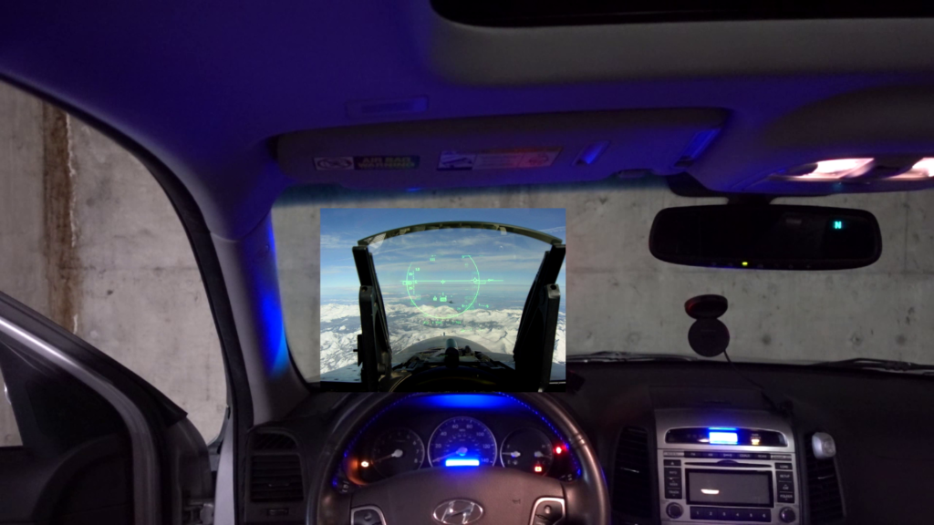
I wanted a HUD, Heads Up Display to my car. The main purpose is to let me keep my eyes on the road and still be aware of my speed without looking down, hence “heads up”. This idea has been used in fighter jets for decades now.
I do not like any of the other ones on the market today, they all try to do “too much”. I wanted something more simple and elegant.
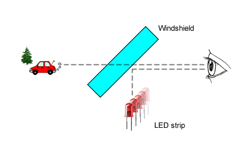
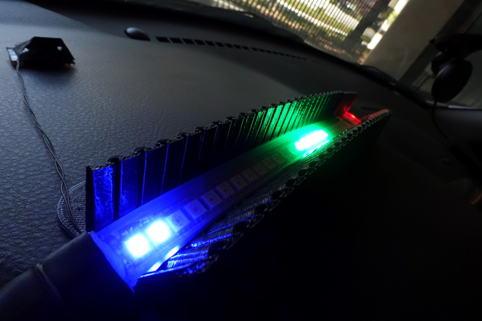
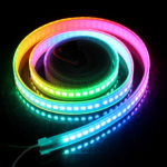
My design is a simple RGB capable individually controllable LED strip that reflect off my windshield.
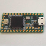
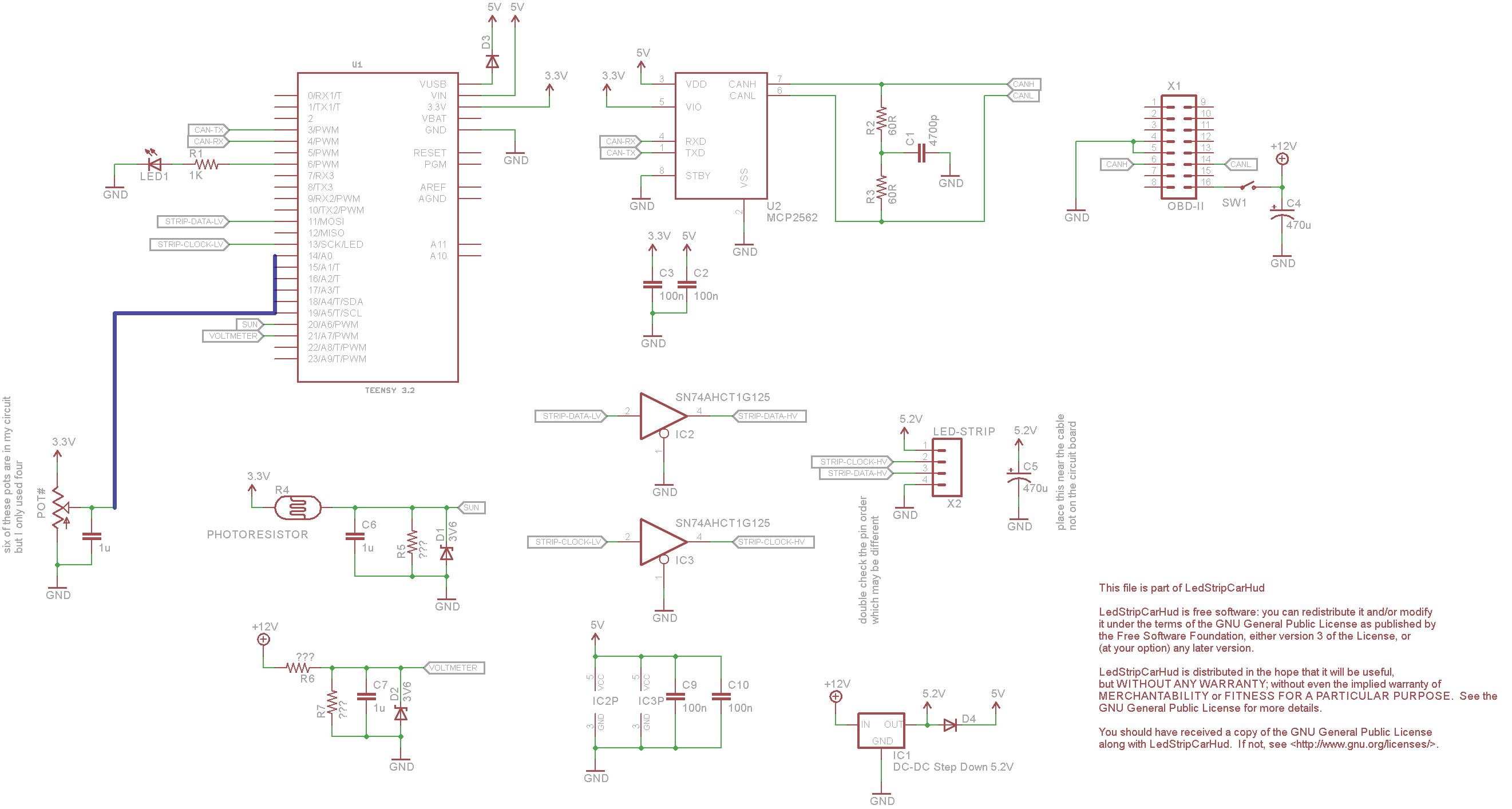
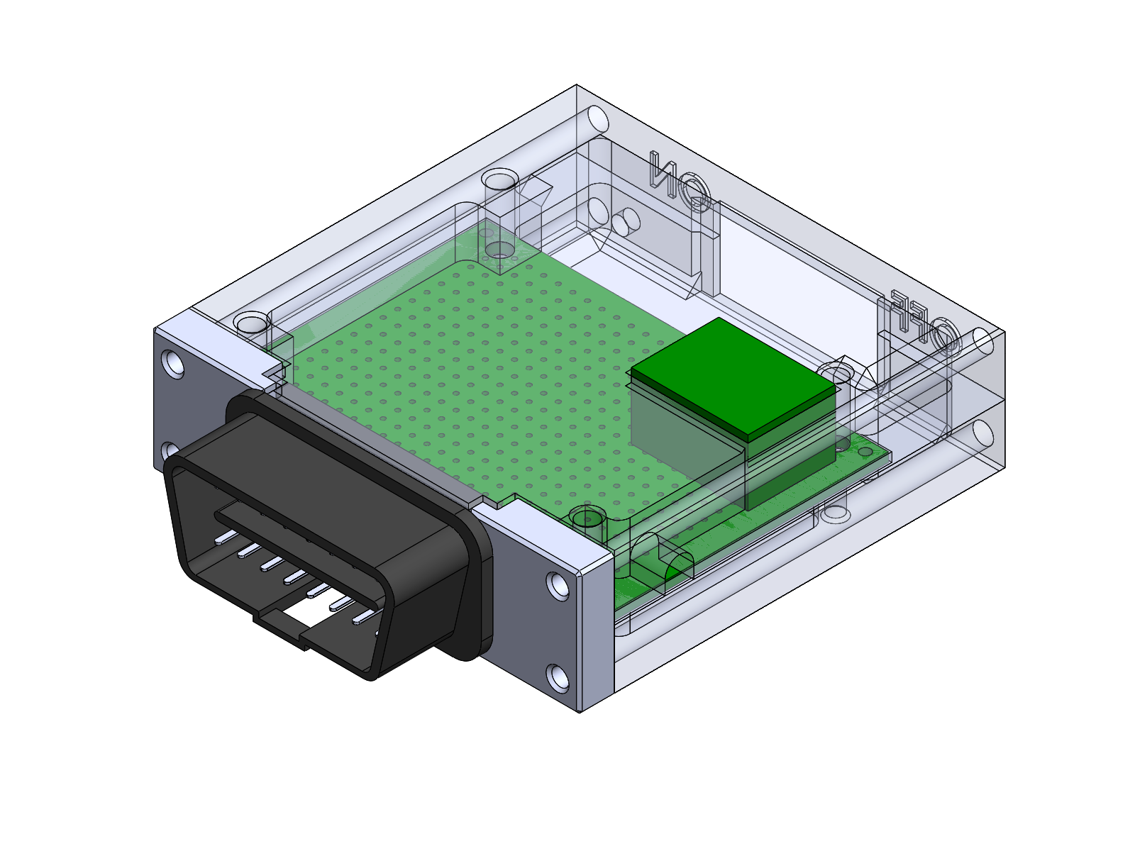
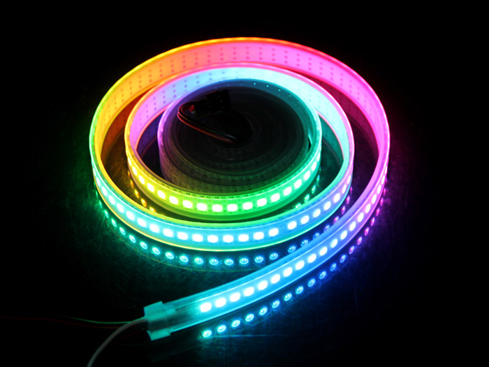
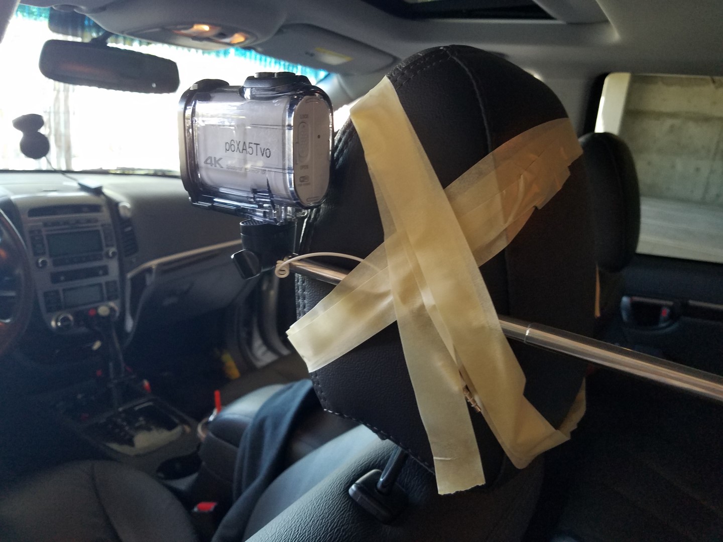
I used the “DotStar” from Adafruit Industries, which uses APA102 LEDs. The brain is a Teensy 3.2, which is connected to my car’s CAN bus via a OBD-II connector (the diagnostic port that you can read the engine computer from).
It is programmed to have three different modes: voltmeter, tachometer, and speedometer. The mode switching is “context aware”: When the car is moving, the mode changes to speedometer. If I rev the engine without the car moving, the mode changes to tachometer. When the engine is off, the voltmeter shows me the car’s battery voltage. When transitioning between the modes, there’s a few preset transition animations that are randomized. When the car is off, the circuit goes into sleep mode. Click play on the video below to see a demo:
Another video with a wider point of view:
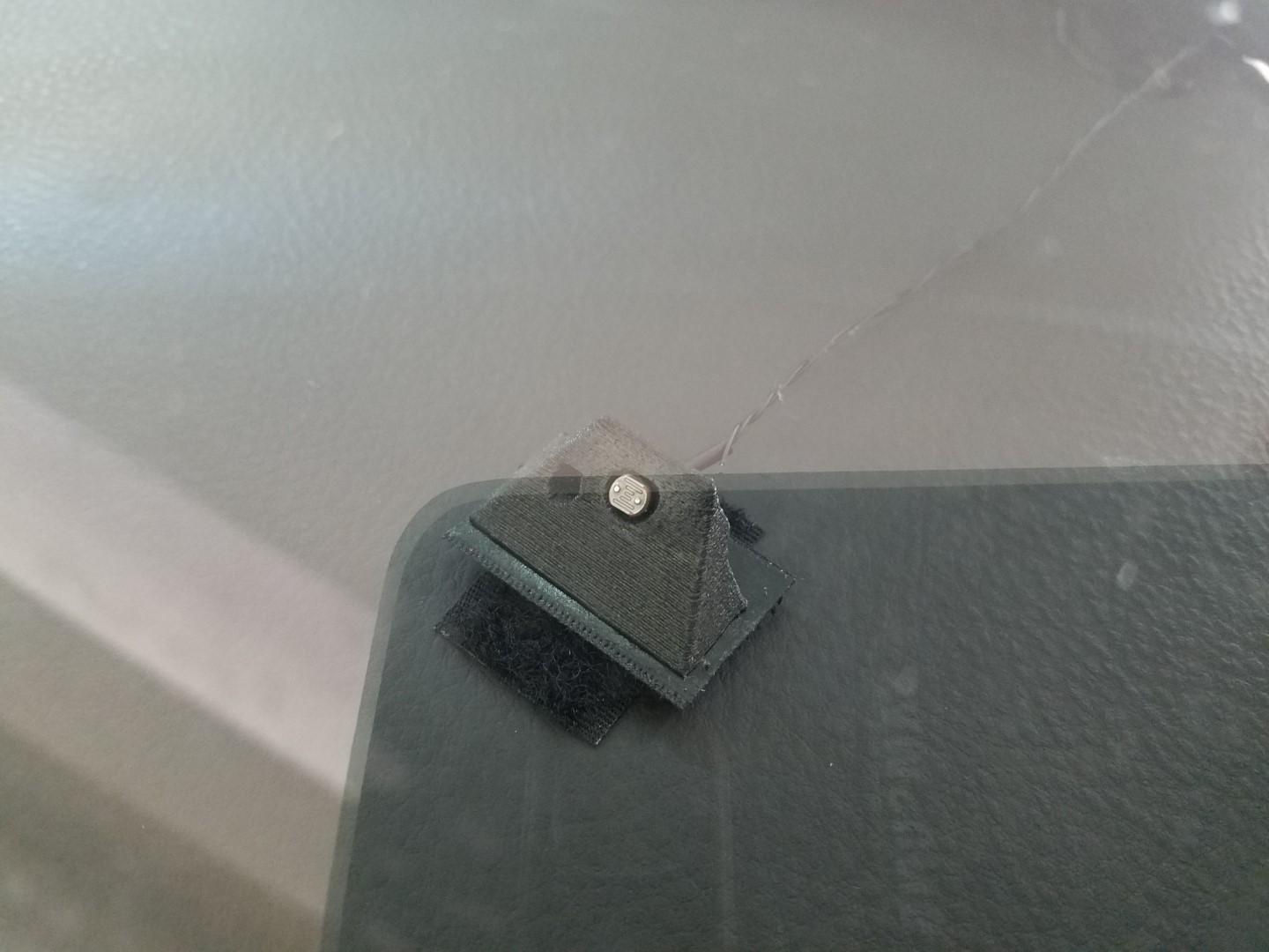
There’s a photoresistor that detects how much sun light there is and the firmware will adjust the LED brightness accordingly. This is actually incredibly important, the LEDs are only visible enough under bright sun when they are at maximum brightness, but maximum brightness will burn your eyes out at night.
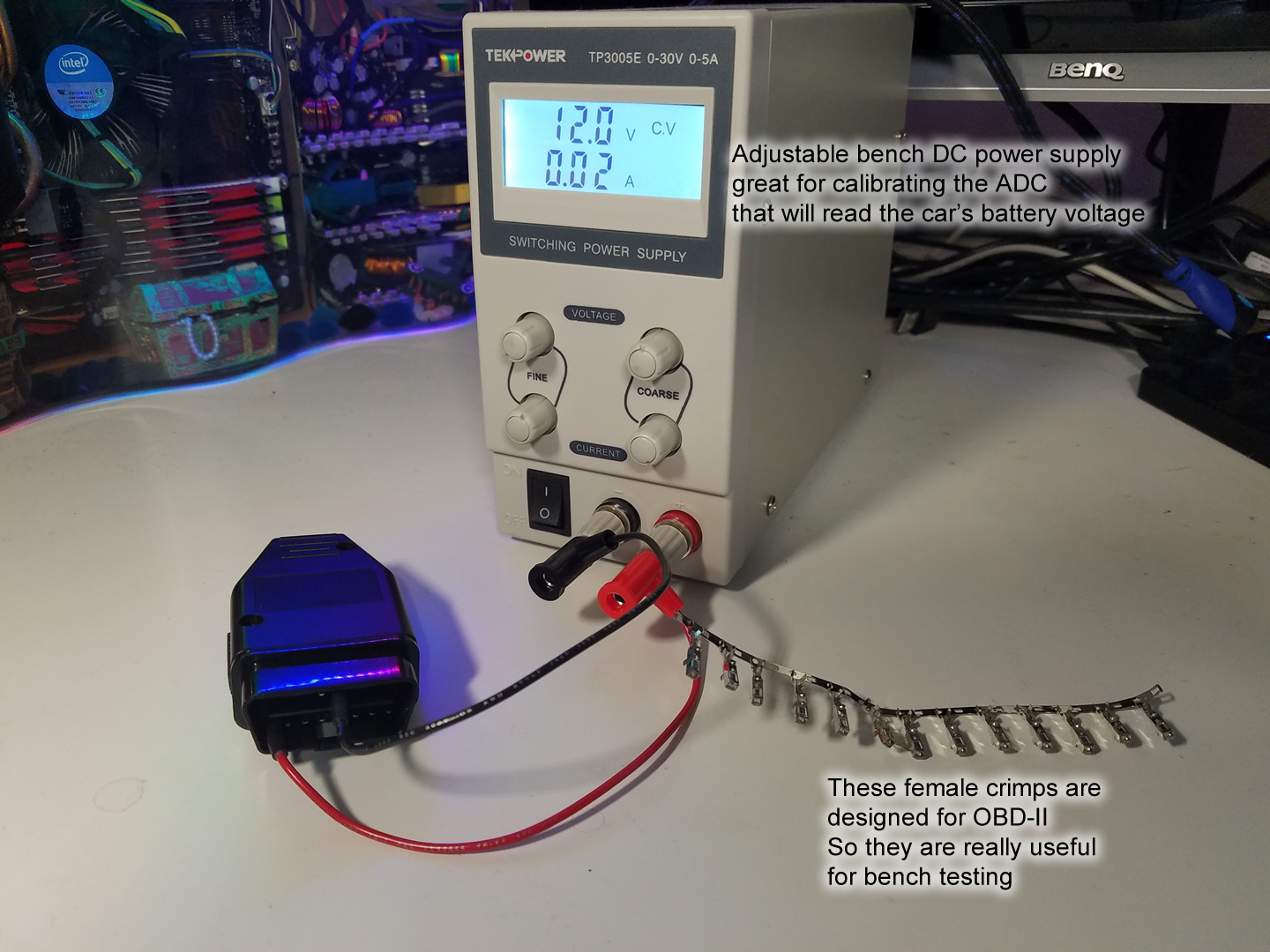
The circuit is built on a small perfboard. It involves a DC-DC step-down converter (3A output capable, adjusted to 5.2V, purchased from Amazon) to regulate the car’s 12V to 5V. The MCP2562 chip is used as the CAN bus transceiver. A couple of SN74AHCT1G125 are used to convert the Teensy’s 3.3V pin voltage to the LED strip’s 5V input voltage. There are half a dozen trim-pots connected to the Teensy so I can tweak brightness and voltage calibration without re-programming the Teensy.
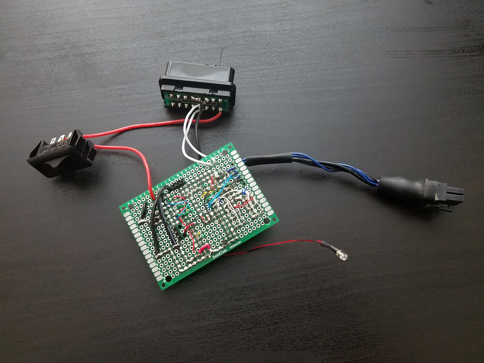
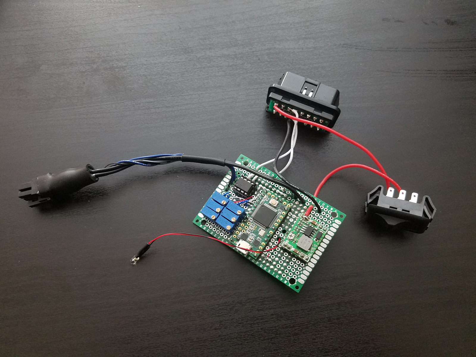
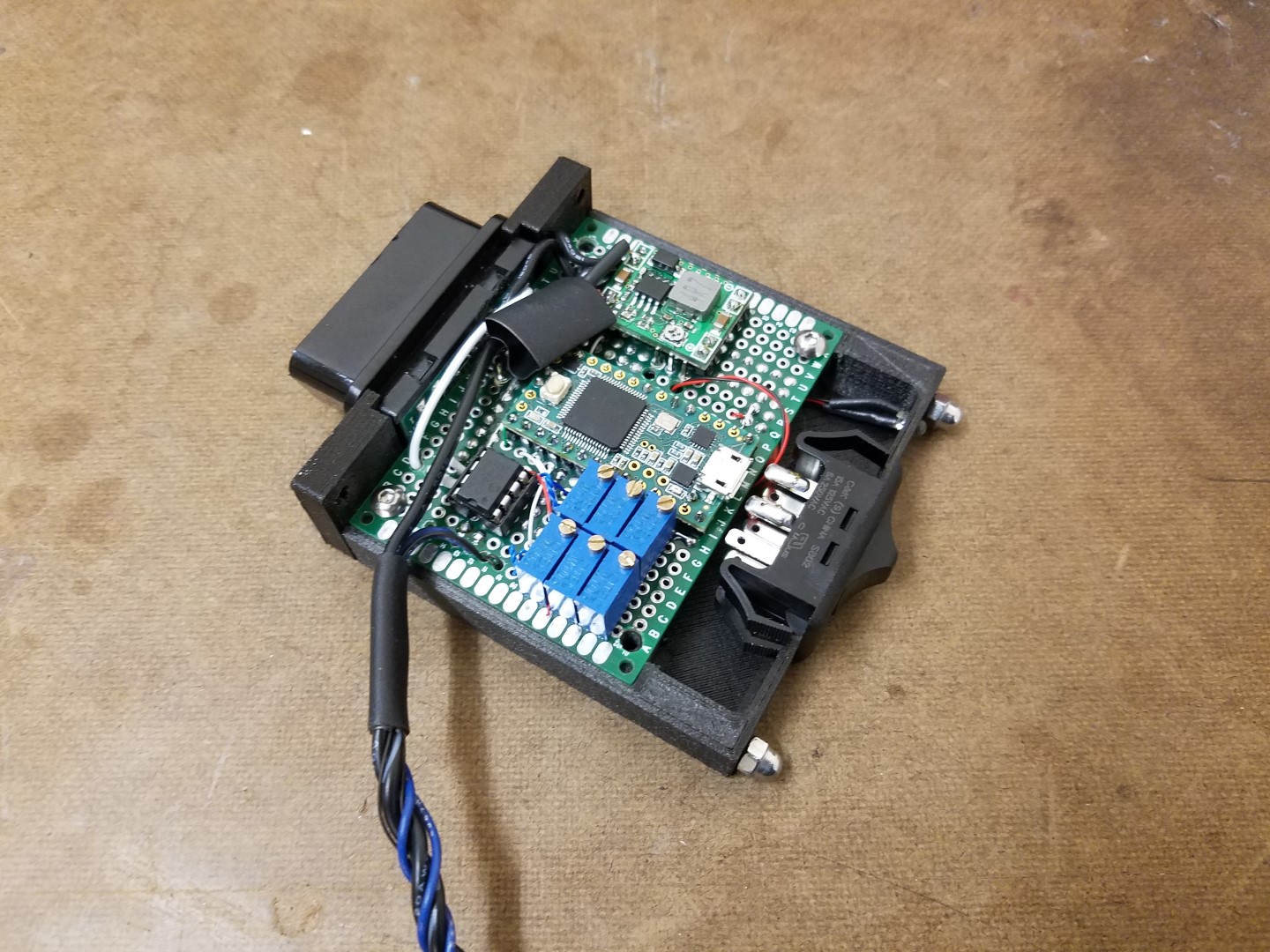
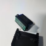
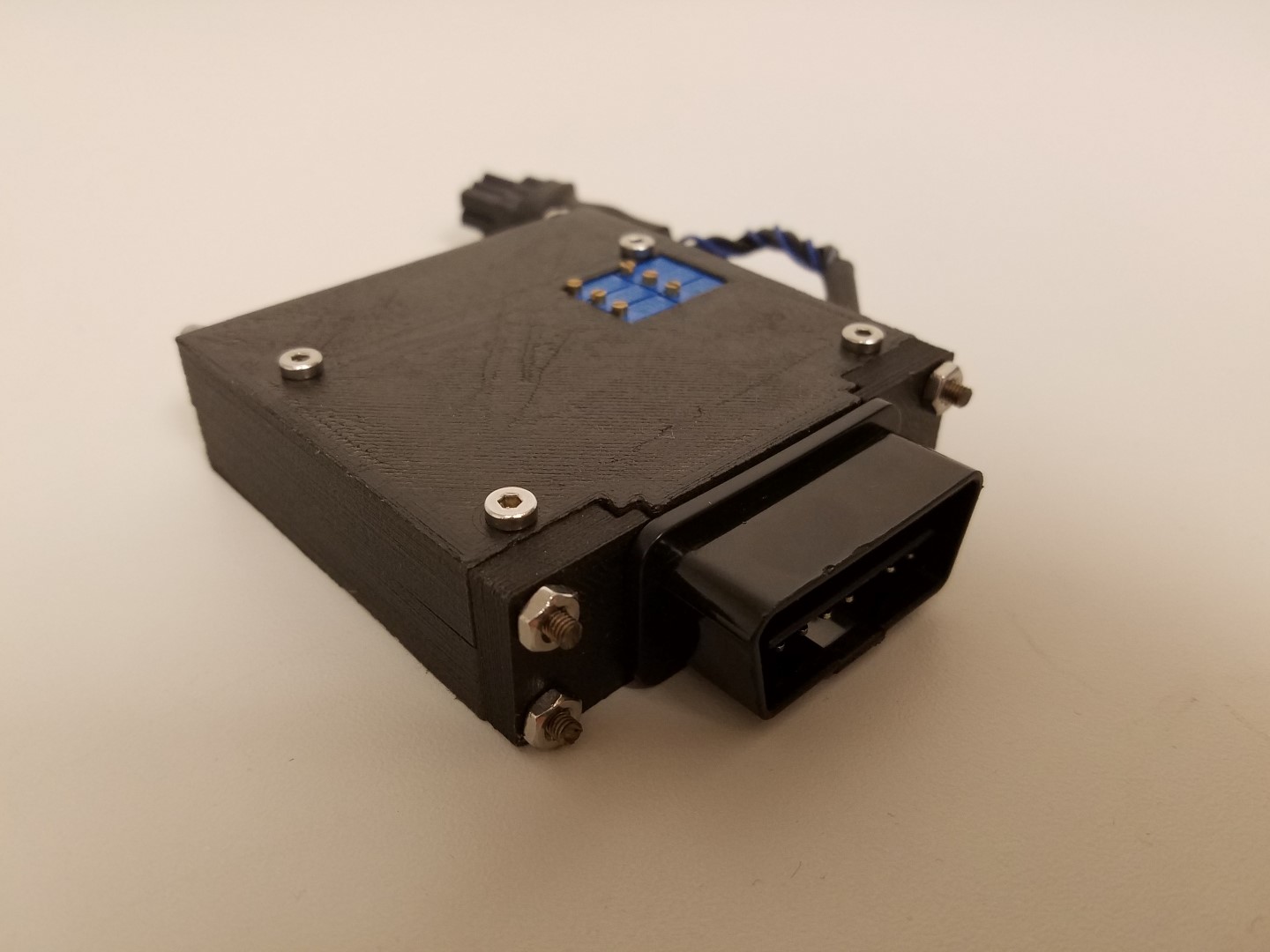
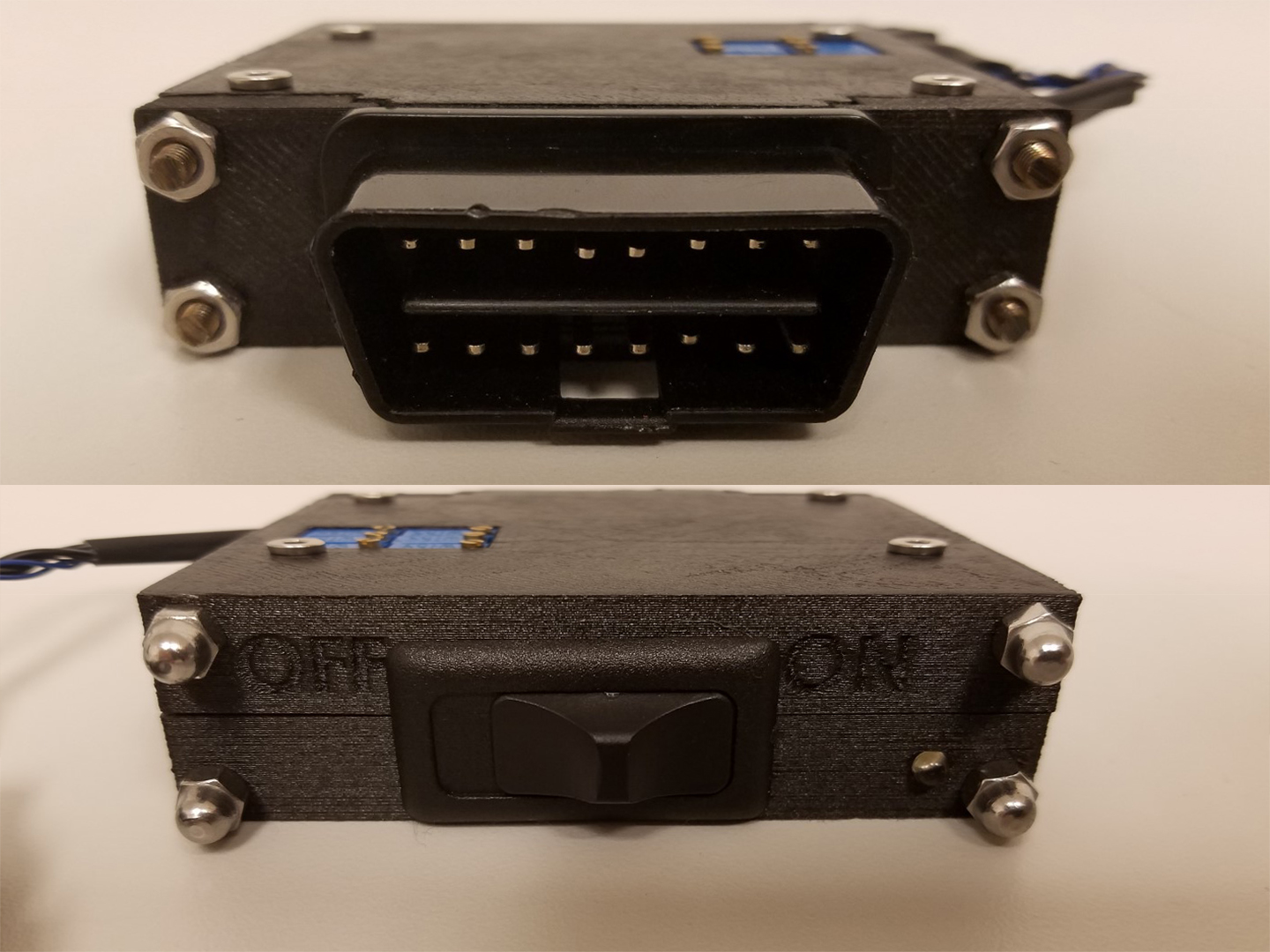
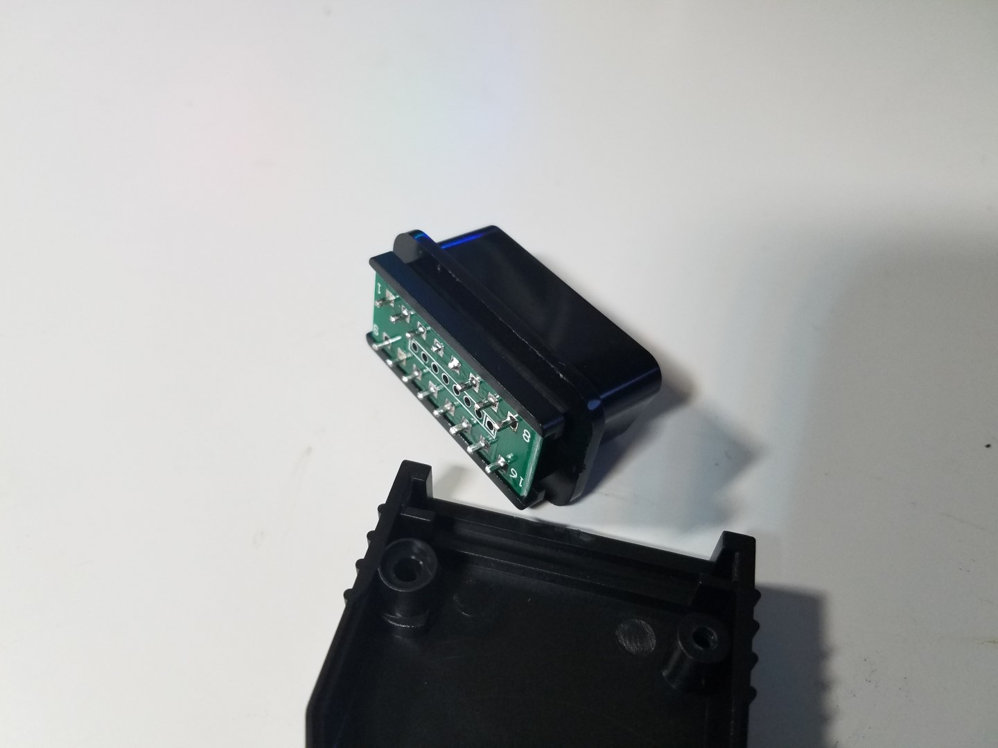
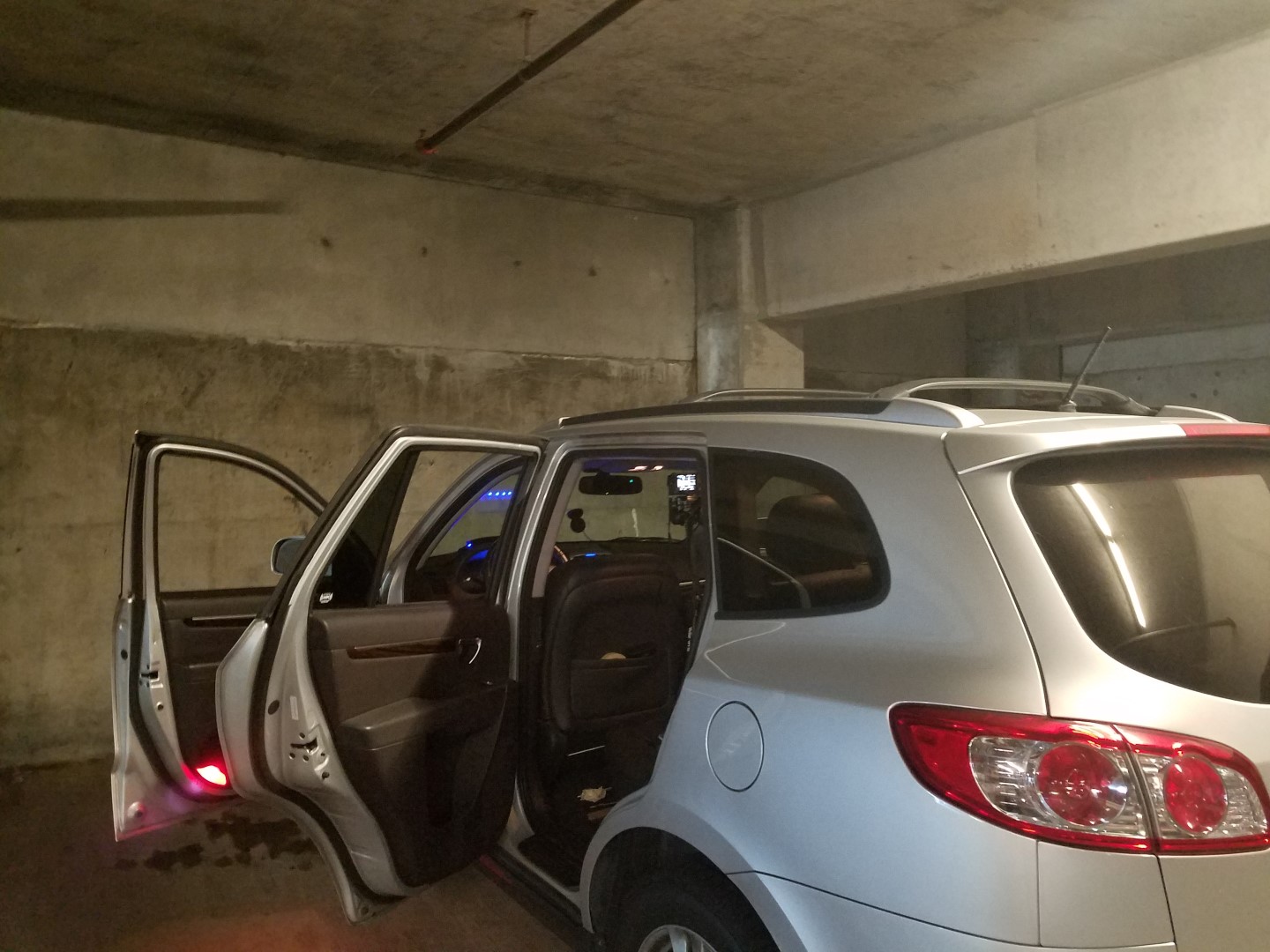
I obtained the OBD-II connector through Amazon, drew up a 3D model for it, and 3D printed a box that fits the connector and the circuitry, so it plugs right into the OBD-II port on my car. The material used is a nylon and carbon fiber composite (NylonX), making it strong and heat resistant. (This filament is awesome! Highly recommended. All of my upcoming robots will be using it.)
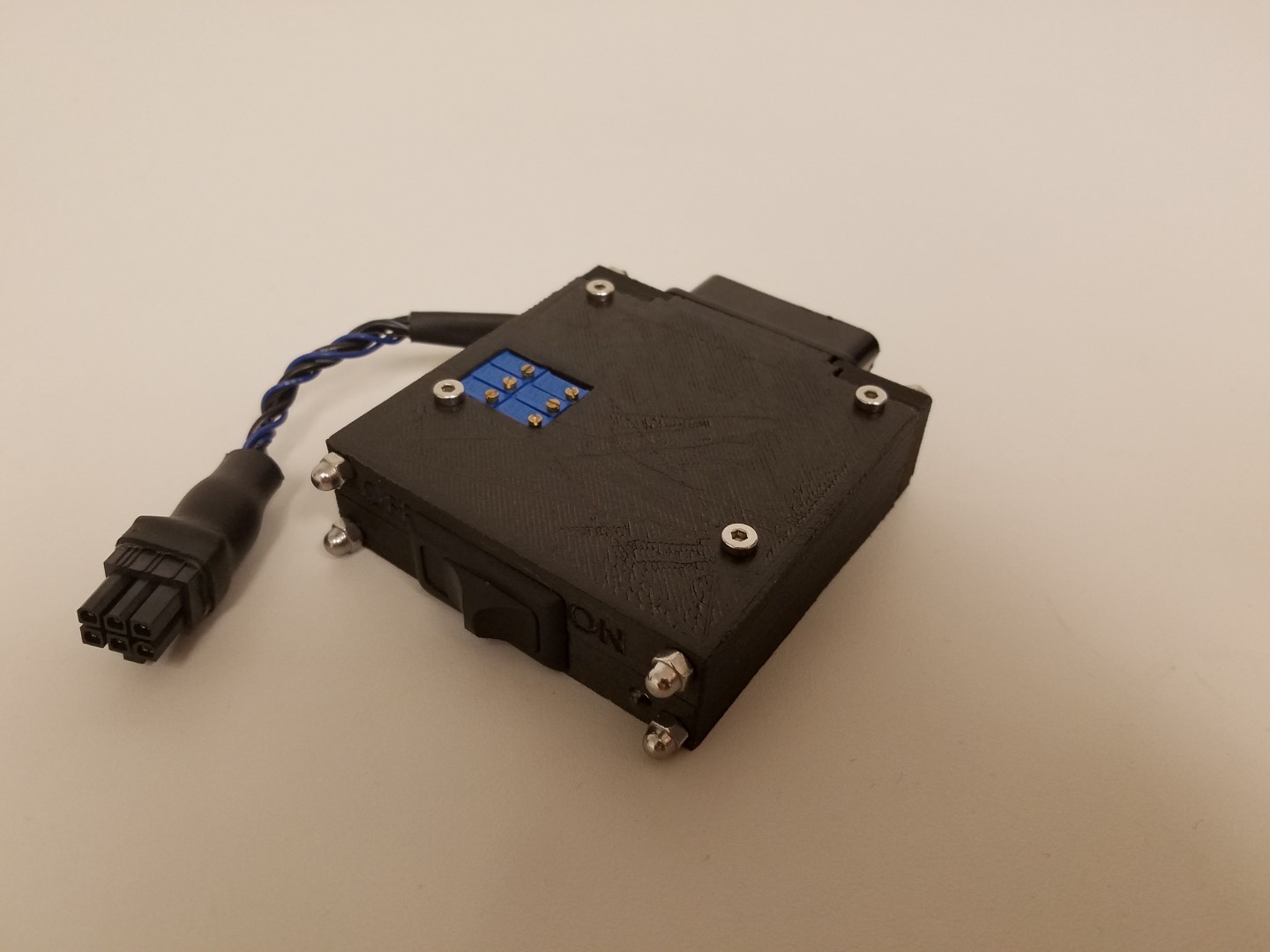
About 3 feet of cabling connects the strip to this box, 22 gauge wire for the power and a shielded cable bundle of 28 gauge wires for the signals. At full load of 3A, the end of the strip still saw 4.8V (keeping in mind that I am feeding 5.2V).
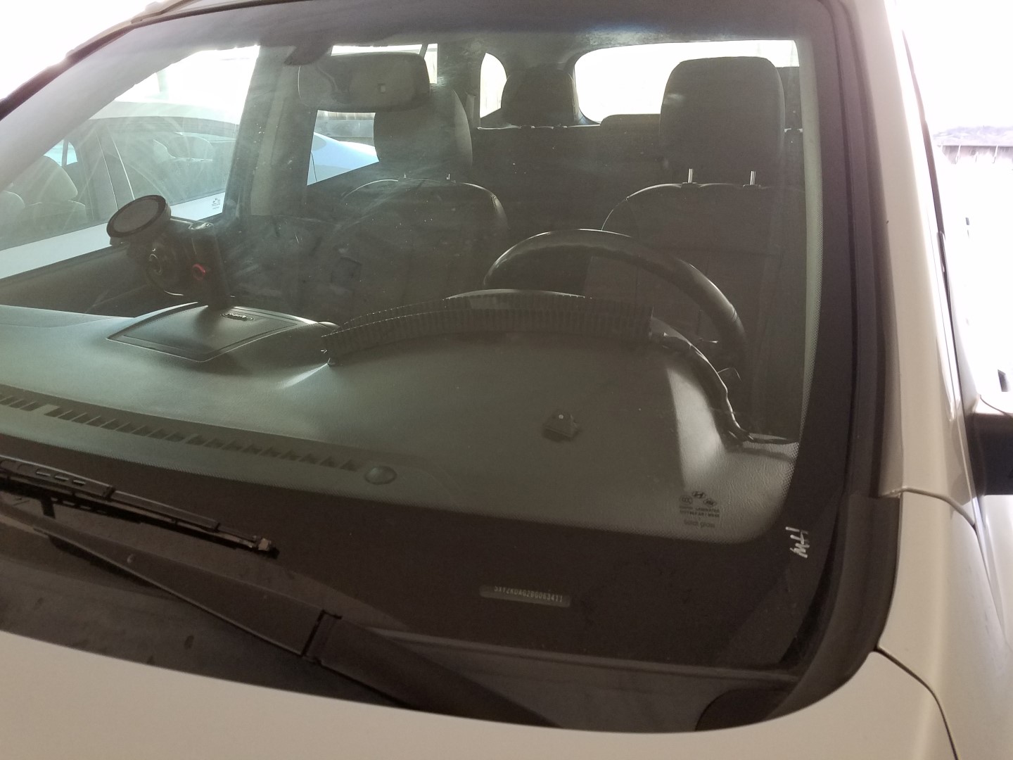
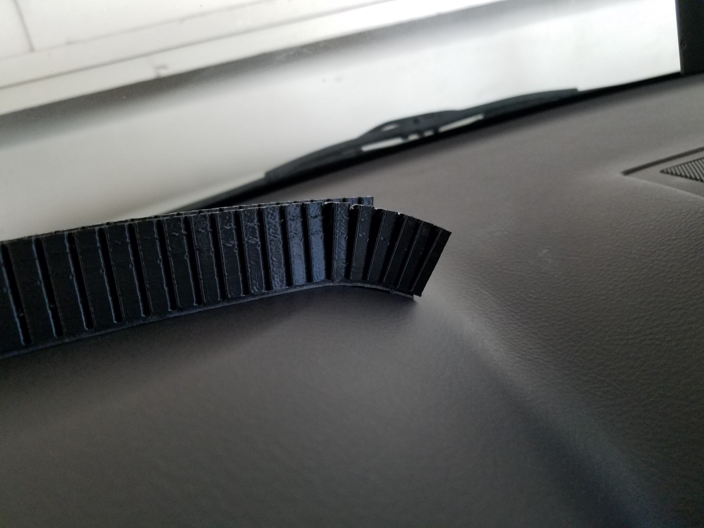
The LED strip has a 3D printed shroud to prevent the strip from distracting me and other drivers (cops won’t be happy about me having red and blue lights). I should only be seeing the reflections off my windshield. The material is called nGen_FLEX, which is a NinjaFlex knockoff by ColorFabb. I needed it to bend and form against my dashboard for easy mounting, so I’ve designed it with gaps that are bridged with a curve that allows the gap to grow more at the top, which allows it to bend easily. Think of an accordion.
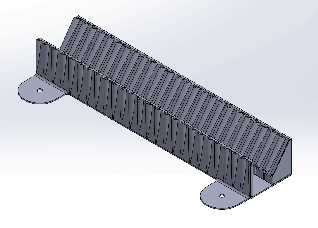
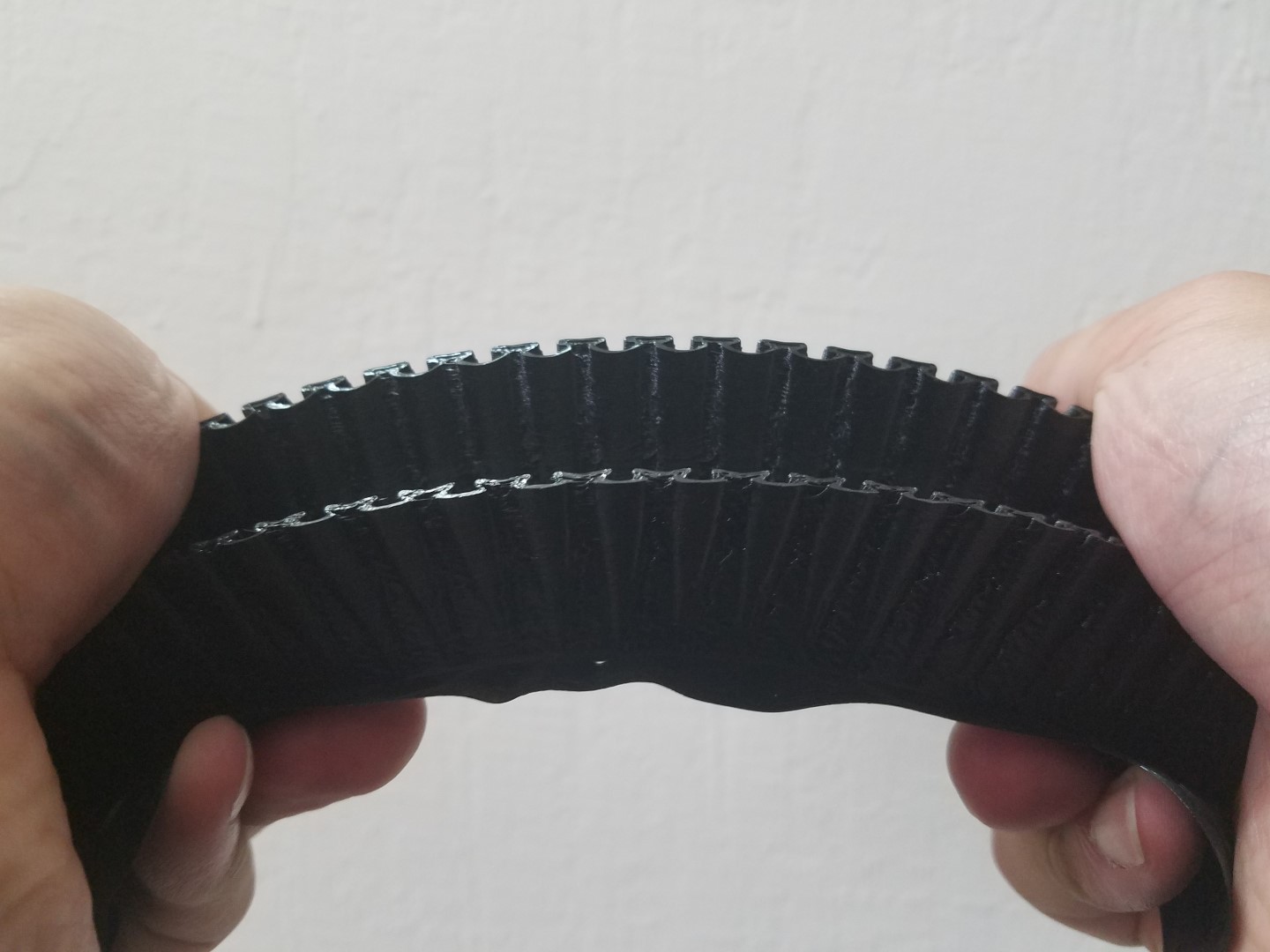
(Honestly I don’t like this nGen_FLEX filament, it’s stiffer than TPU and has worse shrinkage and worse bed adhesion than TPU, but it required less extruder calibration. It works well for this project but I had to print everything with brims just so the print jobs don’t fail.)
More Pics
Here’s some of the animations under bench testing (click play on the video):
The voltmeter mode and tachometer mode both have more different animations.
Technical/Engineering Lessons and Notes
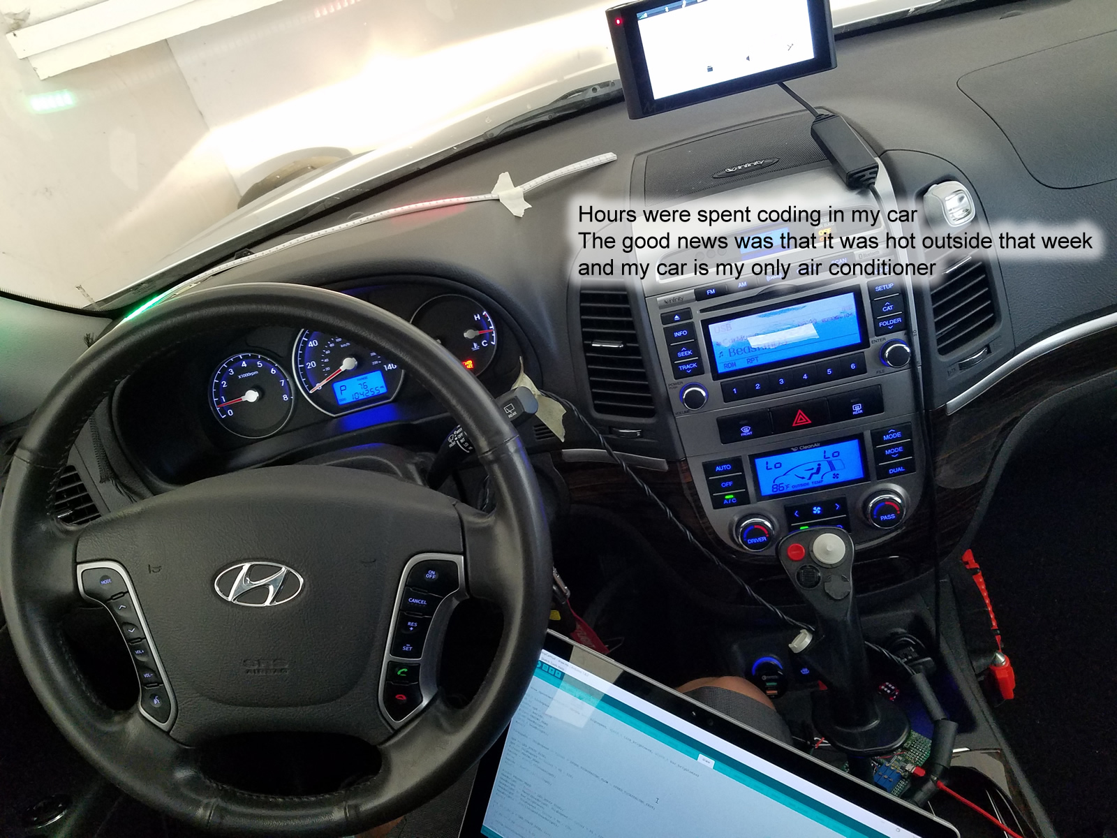
What you’ll see is simply a line of LEDs, but what it took was weeks of designing, building, repeated testing with minor iterative UX changes, hours coding while sitting in a car, gallons of gas burnt driving to nowhere with different speed limits and during different lighting conditions. It is something I will use daily as long as I keep this car, so everything has to be perfect, aesthetically pleasing, safe for me and other people, and durable.
- At full load, the LED strip becomes glitchy. I am sure this is not due to bad cabling or signal integrity issues on the SPI bus, so I am suspecting the step-down converter of being noisy. I am simply too lazy to drag my oscilloscope down to my car to make sure. I added a auto-dimming feature that estimate how much power is being drawn and adjusts the brightness of the entire strip, and then this problem went away.
- Holy shit there’s a lot of traffic on the CAN bus. Without implementing proper message filtering on the Teensy, the Teensy actually becomes overwhelmed with messages, making reading data impossible. I am sure some of these messages will be fun to investigate.
- My wake-up routine from sleep mode involves multiple polls to the ECU. I think it’s polling too much, my key-fob stops working until the ECU is rebooted. Switching to a single poll seems to have resolved the problem.
- Reversing the two CAN bus pins will make your dashboard light up like a Christmas tree. Your ECU will also report a U0101 error, which you can simply clear.
- Warning: the images of the DotStar strips on Adafruit’s website may show pin positions differently than what you receive. The only way to know for sure is to test.
- Using super glue to fix the voltage of the DC-DC step-down converter seems to work great.
- My car’s CAN bus runs at 500000 baud. The FlexCAN library’s default is 250000.
- The LED strip’s own light can feed back into the photoresistor… Not too much but when I noticed, I laughed a bit. This problem was resolved by mounting the photoresistor at an angle, farther forward, and the shroud also helped.
UI/UX/Psychology Notes
- A pure bar graph (as in, using a continuous bar) to display information obstructs too much of the driver’s view, so I switched to using a moving “needle” that is 3 LEDs wide.
- Having the brightness of the leading and trailing LED of the “needle” fade gives a much better illusion of movement, and is less distracting.
- I chose to use colours that are not green, to prevent myself from confusing them with traffic lights. This turns out to be a non-issue. It feels like there are many other visual cues at play and even if I used green, I was always able to differentiate between my LEDs and the actual traffic light.
- Having all blue ticks didn’t work well because it was hard to count the number of blue ticks your needle has passed. The solution is to make the ones your needle has passed red, but not the “zero”
indicator. For example, if you see 3 red dots, you can immediately think 30+ MPH. - My virtual “needle” is 3 LEDs wide, with the middle LED resting on where your speed is. But when the right side LED overlaps with a tick, I change the colour of the tick. This is because, for example, if you are at 39 MPH, I want your brain to count 4 red dots instead of 3, because you are so close to 40 anyways.
- The primary speedometer scale is 0 to 80 MPH. I experimented with 0 to 120 and found that it was hard to read and had low resolution. I also experimented with switching between the scaling once the car hits 80 MPH… that was the worst idea ever, it’s additionally disorientating.
- The choice of blue is for its common association with calm, and I don’t find it hard to see against the sky. I don’t even care if it is a bit harder to see against the sky as the blue ticks indicate a speed you have not reached. The red dots on the left is just a classic choice. The needle is orange, because I wanted yellow but found yellow to be harder to see under the strongest sunny conditions. It’s not a problem when the orange meets red, they contrast enough and you still have awareness of where the red tick really is from the surrounding ticks.
- Speed of brightness dimming must be slow or else it’ll be incredibly annoying to see the LEDs flicker all the time.
- Having the display above the horizon makes it much easier to read.
Source Code and CAD Files
Everything is open source and on github here. Pay attention to the README files please. There are firmware source code, electrical schematic, and mechanical CAD files inside.
Maybe somebody will take this project to the next level, such as using optical sign recognition technology or a map API to determine the speed limit. For me this was just for fun and another LED art project.
I’d like to stress that messing with your car and test driving stuff like this is not a joke. If you look into the github repo, you’ll see that most of the tests are done on a bench using simulated input. Make absolutely sure you are comfortable with the test results before driving with it.
Oh and remember that the LEDs will be in a hot car right on the dash, they will get hot. I have not tested them in Arizona weather for you.
Thanks to…
- Arduino IDE, normally I don’t use or like it but if I had to use three different libraries written for Arduino, I might as well bite the bullet.
- Paul Stoffregen for creating Teensy and Teensyduino.
- All the contributors to the FastLED library. I hate Freescale’s support for their chips, so while the LEDs are very simple to drive on a SPI bus, this library made it much easier to utilize the SPI peripheral on the MK20 microcontroller.
- All the contributors to the FlexCAN library. Again, helped me avoid using Freescale’s own low level code. The latest versions has a non-blocking mode that uses callbacks, which made it my firmware perform much better.
- All the contributors to the Snooze library. Such a great way of implementing power saving modes.
- Background music in the video: Corporate Technology by Scott Holmes. Creative Commons Attribution-NonCommercial
My Design vs Other Designs
- Other designs sometimes require a reflective sheet to be installed on the windshield. This is because they can’t get the brightness high enough. In comparison, my LED strip concentrates more power into individual dots instead of diffused segments, so while I convey less information, it is easily visible even during bright sunlight. Also, my dots do not suffer from the “double reflection” problem due to the thickness of the windshield, both due to the brightness and to the fact that they are dots.
- There are designs out there that are simply a mirror over a phone, these costs around $10. If you like plugging in your phone every time for this, or buying a new smartphone, then go for it.
- The augmented reality projection HUDs are actually pretty cool. They have optics that projects the image much further out. They are expensive and come with features I don’t need, such as navigation and phone calls. I have a very nice Garmin nuviCam that can beat that in terms of features, it even has collision/lane-depart warning. So if Somebody makes a HUD that can replace my Garmin nuviCam, with Garmin’s level of UX design, I might reconsider.
- Garmin actually has their own HUD but it requires a reflector sheet and a linked smartphone. I’ll pass…
- Obviously mine is designed for automatic transmission cars. I like how simple mine is in comparison to something with a ton of useless information displayed all at once. Those other LED segment models have around 16 menus for you to configure different things. Mine is designed by me for me so I don’t dick around with any settings.
- My design has a much more rapid update rate than most other designs. Mainly because it’s hard to read a rapidly changing 7 segment display but it’s easy to read a moving dot. That’s why I chose to use a LED strip in the first place.
- I can adjust my HUDs position to be much more eye level than any other design. I actually prefer mine to display above the horizon.
- One of the Amazon products said “Notice:Some buyers told HUD can not power off automatically after car power off.The reference start/off voltage is 132, but sometimes after your car power off, bettery may still offer current for HUD, so you should adjust your Reference voltage 132 to 135~138.so that it can automatically power on/off”.
- Are you serious? I solved that problem before the hardware was built… There are so many statistics to check if the car is on or off, starting with… if it’s actually spinning? RPM = 0 means car is off guys. If your car is smarter and shuts off the engine during stops, then your alternator isn’t going to boost your battery anyways. I would simply increase the timeout to 5 minutes in this scenario.
Principle Photography
Outside Mentions
How/where did you learn about the OBD code etc? I am planning to do a similar project, and it involves ODB code.
I actually learned a lot just by reading Sparkfun’s CAN bus shield example code: https://github.com/sparkfun/CAN-Bus_Shield/blob/master/Libraries/Canbus/Canbus.cpp
A big list of PIDs is also available from Wikipedia: https://en.wikipedia.org/wiki/OBD-II_PIDs
Thanks.
Good work there.
I worked on actual HUD systems in fighter jets and one thing that made them really work well was that they used what appeared to be some kind of Fresnel lens in them that changed the focal point of what was on the HUD.
This principle is also deployed in red dot rifle scopes (also called reflexive or holographic scopes). The dot is actually focused on as if some distance from the eye.
Check in this link here for the case where a technician linked a tiny HUD for his eye and his multimeter and the focal point of the lens he used puts the statistics at roughly 30 cm
http://hackaday.com/2017/06/04/__trashed-15/
Now with the fighter jets, while I’m not entirely sure, what I read on those HUD systems is they used a kind of Fresnel lens to give the HUD an “infinite focal point” or something like that.
I know what you are taking about, last year I was designing a reflex sight for fun. From what I found, that type of sight uses a spherical lens that is centered on a point light source like the end of a optic fiber or a laser diode. There is another kind where the light is collimated first and reflected on flat mirrors and lenses, these are popular for telescopes, simple to make and telescopes don’t need to be ultralight. I am pretty sure that’s similar to what the old WWII planes used, and probably the newer jets. Insert a LCD into the light path and I’d be able to project text.
But that requires a flat windshield, I think, and enough room on the dash, even with a fresnel lens.
Only a short stub article, but more here about virtual images in free space
https://en.wikipedia.org/wiki/Aerial_image
Hi, nice job! I will try do the same using a 7 segments display. I see in your LED strips specification the bright of red light is 600 mcd. I found 7 segments display with 8000 mcd in specs, so, it will be visible at sunlight too, right?
Wikipedia says candela is used to measure ideal point light sources. I am not sure how that applies in your situation. 8000 sounds like a lot for just one point, if it’s the total brightness of all 7 segments, then I suspect it’ll look quite similar to mine.
If 8000 mcd is the brightness of just one segment then you might have a large multi-led-per-segment displays, it should work fine, yea it’ll probably be brighter.
Try it out.
You might need a reflector film, not because it’s not bright enough, but because you’ll see two reflections and you want one to be more visible than the other.
Perhaps if I use a fresnel lens I can dispense the reflector film?
Great project!
Will I get the exact LED strip from Amazon which you have mentioned in this article ??? I am very excited to make my dashboard very attractive. I liked the way the author has described the details.
Adafruit is a better choice for most of the electronic goodies. Sparkfun is my second choice.
Can you recommend hobby bench power under $100