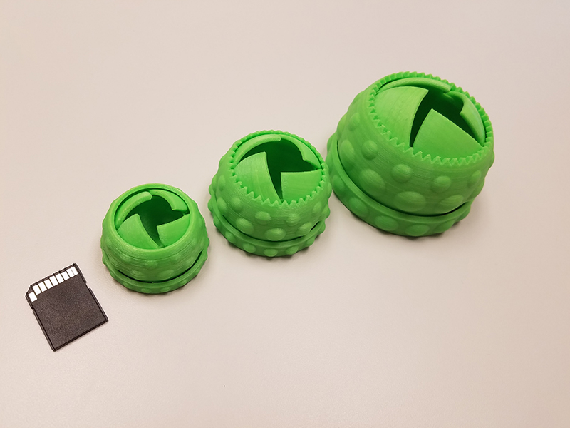
It’s that time of year when we think about gift giving. I decided to design a dome shaped box that opened with moving curved doors.

(dear iPhone users, sorry if the videos don’t work for you, please consider upgrading)
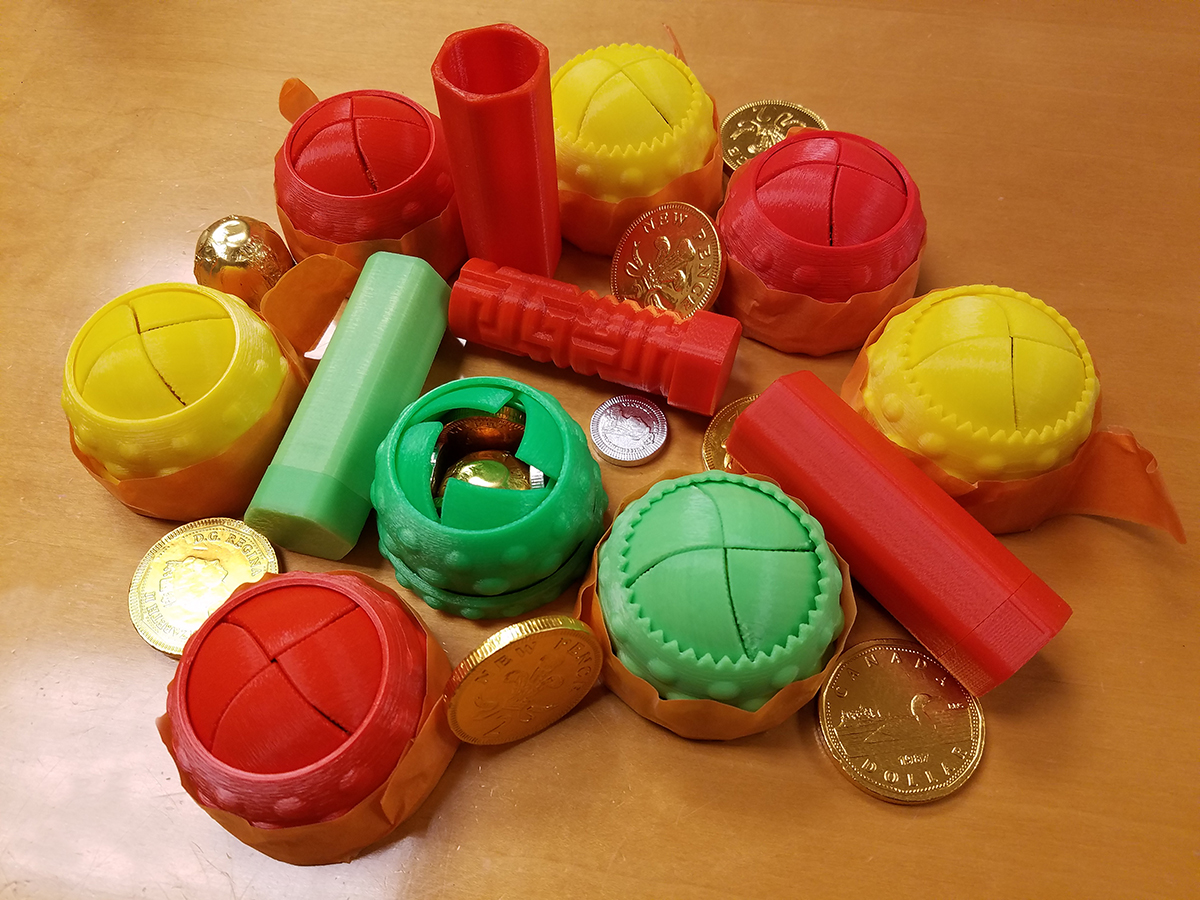
Keep reading for more pictures and a full tutorial teaching you how to create this in CAD.
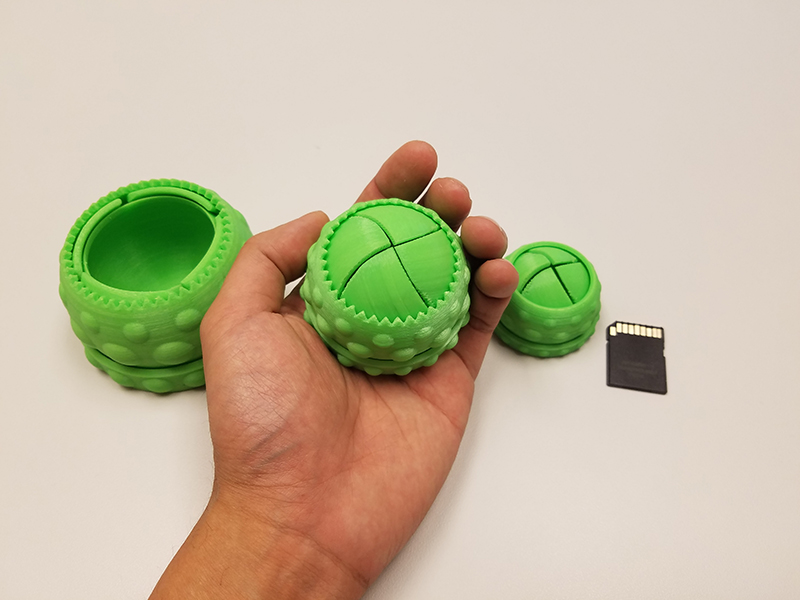
What makes this extra cool is that all of this is 3D printed as one piece, there is no assembly required!
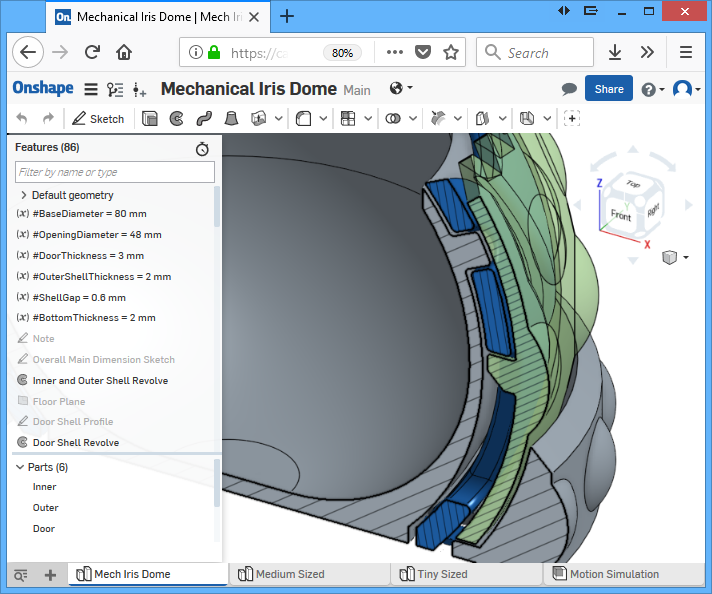
I will show you how I designed this, step by step (plus why I did it that way), using a mechanical 3D modelling CAD tool called Onshape. I will focus on the things that showcase the power of a “parametric feature based modeling” CAD tool, and how it eliminated some of the problems me and other people have faced with other similar designs. When I modeled this design, I paid extra attention for the dimensions to be adjustable without compromising the 3D-printability of the design.
Simple Explainations
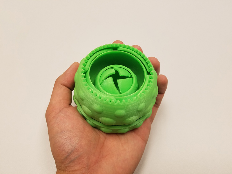
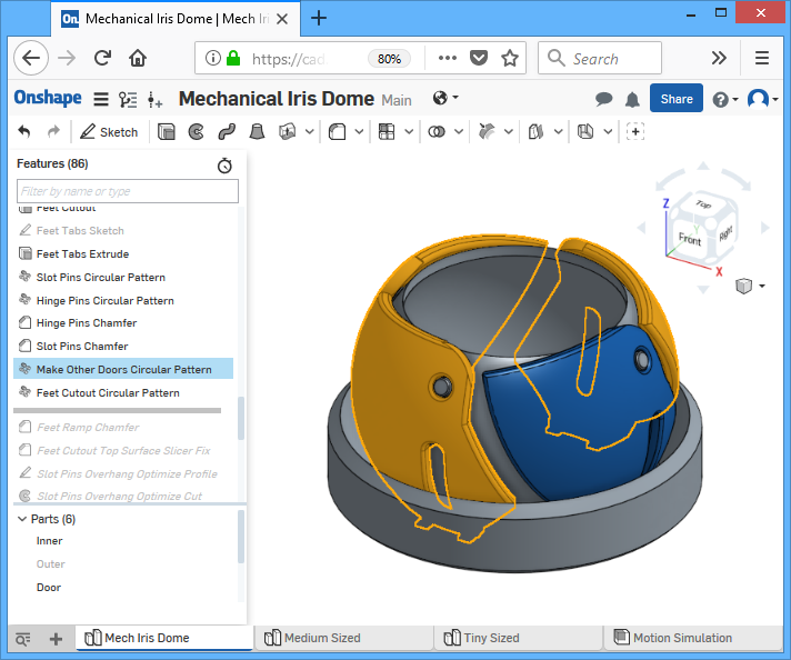
First, take a good look at the animation of how this box actually works. There are two shells that sandwich a set of door pieces. The door pieces rotate about a hinge that protrudes from the inner shell. The door pieces also have a slot that bounds a pin, the pin protrudes from the outer shell. As the outer shell rotates clockwise, the pin pushes against the slot, causing the door to rotate upwards. Rotating the outer shell in the opposite direction will cause the door to rotate downwards.
To understand how it is possible to 3D print this device “all in one piece”, there are several point in the design to notice:
Obviously, all the pieces are separated by a small gap, between shell faces, around the hinge, and around the slot. If any gap is too small, then there is a risk of printing artifacts and imperfections jamming the mechanism. If the gaps are a tad too big, then the mechanism will be more “loose” feeling, just a less pleasant experience playing with it. If the gaps are huge, then the entire print will come apart in pieces, definitely not good.
The doors are actually attached to the bottom during the printing process. There are several tiny tabs that join each door’s “foot” to the rest of the body. All of the body, including these feet, are glued to the 3D printer’s build plate during the printing process. This holds the doors still during the print, otherwise, the door will topple during the print. After the print is finished, the tabs are cut using flush cutters or a knife, thus freeing the door pieces.

The outer shell is separated from the inner shell by a very fine gap. This gap is just small enough for some plastic to stick the outer shell and inner shell together during printing, but also large enough to make this connection very weak, thus it is easy to break free. This connection is only broken after the print is done. After that, the outer shell is held captive because of its curvature, it still does not have a large enough opening to escape the other pieces.
{ Earlier Designs and Problems
(you should skip this section if you don’t want to hear me criticize other people’s work, there’s an arrow you can click on to “unhide” this long block of text)
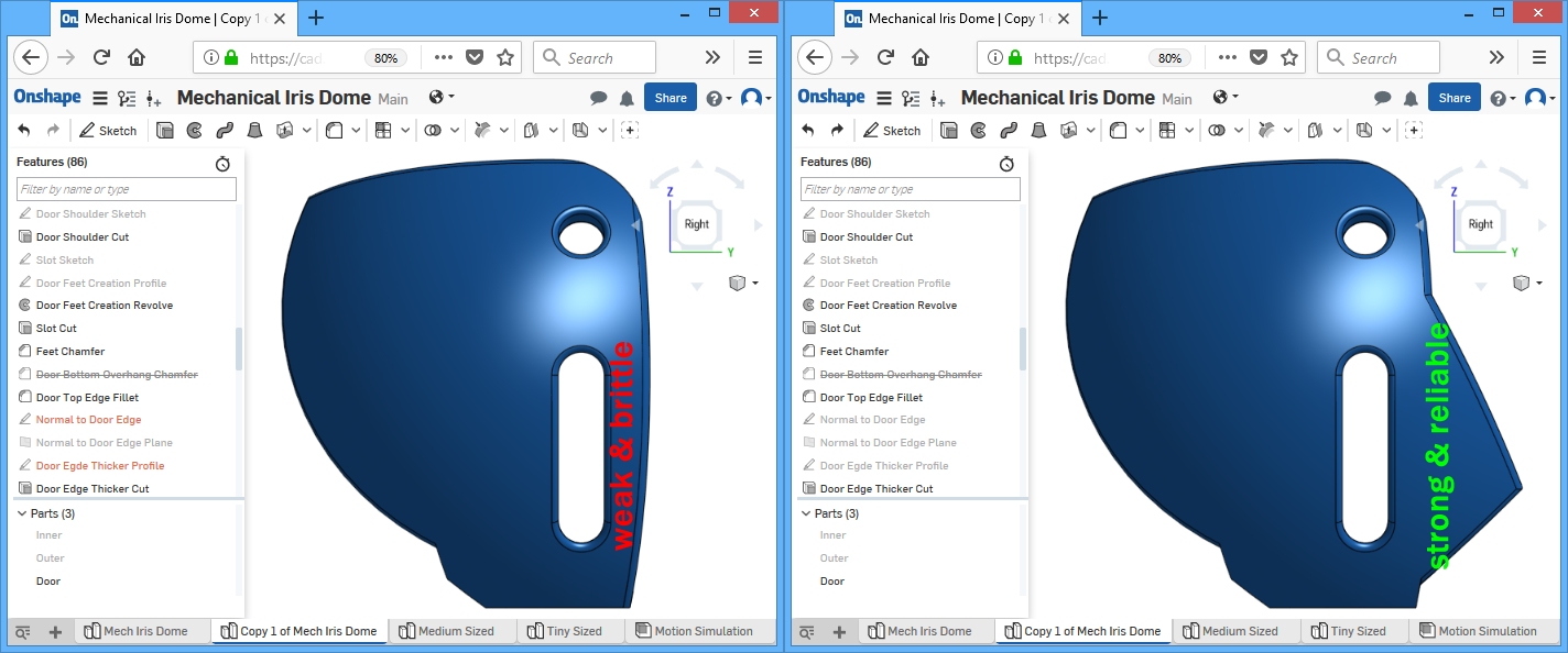
Both of these designs (in their original state), when 3D printed, are delicate, and fails almost every single time during the print or during post-processing. The walls are just too thin, there are many overhangs that cannot be cooled fast enough because there are walls blocking the airflow. What this means is that the door pieces will curl upwards during the printing process and then when the printer’s extruder travels over the curls, they collide, and the wall can break. With my 3D printer, the room it’s in, and the PLA I am using, I can’t make this thermodynamic problem go away using thermodyamic solutions. A simpler solution is to just make the model thicker, obviously stronger, and it will curl less as there’s more plastic holding down the curling force.
Making the model thicker in emmett’s OpenSCAD code should be easy, he named a variable “T” for the thicknesses, but no offense to him, I just don’t like how the rest of the design looks. I thank him for being the inventor (as far as I know) of this mechanism but I will not be using his code as is. The code is also uncommented, and the only design intention being implied are from the very short variable and method names.
LocoCNC posted his SolidWorks file, but unfortunately, while simply changing the wall thickness seems simple, doing so seem to change the curvature geometry of the doors so that they don’t close perfectly. When I checked how the curvature was created, I found that the dimensions were hard-coded as fixed numbers, not equations, constraints, or relationships. Also, I feel some features were used improperly, often used as “band-aid” solutions to create a particular look, and this caused the features of the model to “break” every time something was changed. None of the features in the feature tree are named so it’s hard to follow design intent.
I decided it’s worth the effort to start from absolute scratch, so I can learn along the way. I will be using a free yet powerful tool so I can share with others, and show how these problems can be avoided.
Earlier Designs and Problems – END }
View, Export, and Print
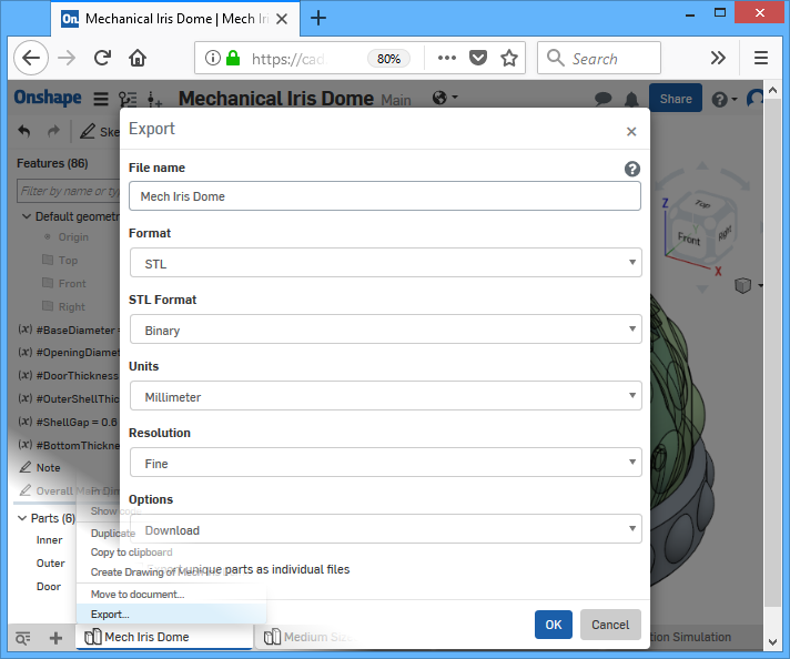
The document is here: https://cad.onshape.com/documents/ce2b47eea2aecc8a5af6d089/w/0dd07bf8a5f9c8a8d7210b5c/e/6c2bb5a57e74b49452e98e1f . Anybody should be able to view it, whether or not they have an Onshape account. To download a printable STL, you do need an account (sorry), right click on the bottom tab and click “export”. To make modifications or to follow along in the tutorial, you will definitely need an Onshape account.
When slicing, make sure you are using 100% infill. It’s best to 3D print this at a lower speed and as low of a nozzle temperature as you can without causing underextrusion or jams. There are hidden overhangs that turn out better when temperatures are lower.
After printing, you need to cut the tabs at the bottom. I use a really sharp flush cutter for this but a small sharp knife will also work. After cutting, it will be hard to rotate at first, try pushing the feet up from the bottom. After it can rotate, you can smooth out the motion by simply playing with it a bit, because it will loosen up some of the hidden debris inside.
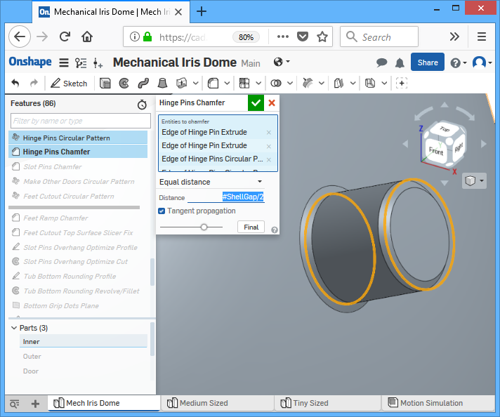
If the resulting print is too loose, or too tight, then go into the model and adjust the #ShellGap variable. I have now used 3 different PLA brands and they all seem to need different extrusion modifiers and different gap widths.
Please do not ask me for STL files. I am actively trying to move the world away from using that file format for sharing purposes.
Tutorial
This isn’t a tutorial on how to use Onshape specifically, I will only be providing a high level guide that does not include exactly what to click. My goal is to teach the thought process behind creating a design in this type and style of CAD tool. Of course, the Onshape document itself is fully open for you to explorer, so it does still show exactly everything I did. The best thing to do is to follow along with the document already open, while reading my written text, interacting with the model itself while reading (use your mouse to highlight things, Onshape will point out all relevant relationships and constraints when you highlight objects). Take it to another level by recreating it from scratch when you understand how.
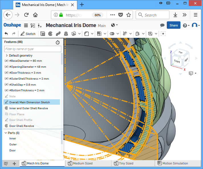
This tool is both feature based and parametric. There is a feature list on the left. Think of each feature as an instruction, and the list is a list of instructions executed in sequence. While my feature list for this design file is very well organized, it was not always that way. The beauty of the feature list is that you can move features and insert features, the final result is neat because I organized it, but when doing the actual modeling, it might get messy.
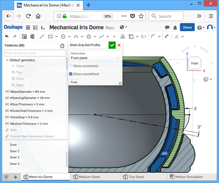
You’ll notice there’s a bunch of variables being declared at the top of the list. I’ll admit that they were not always there. After the design was finished, I decided which dimensions needed to become variables, and put them up top. They have to be up on the top of the list because, as I just explained, features are created in order. If a feature needs a variable, the variable must be placed before the feature. The best way to avoid any errors due to missing variables is to simply always put variables up on top.
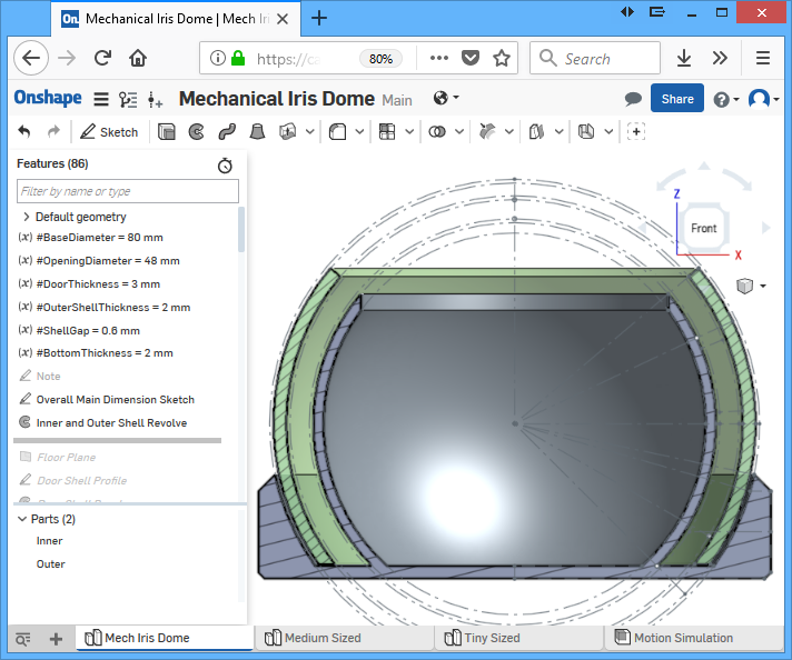
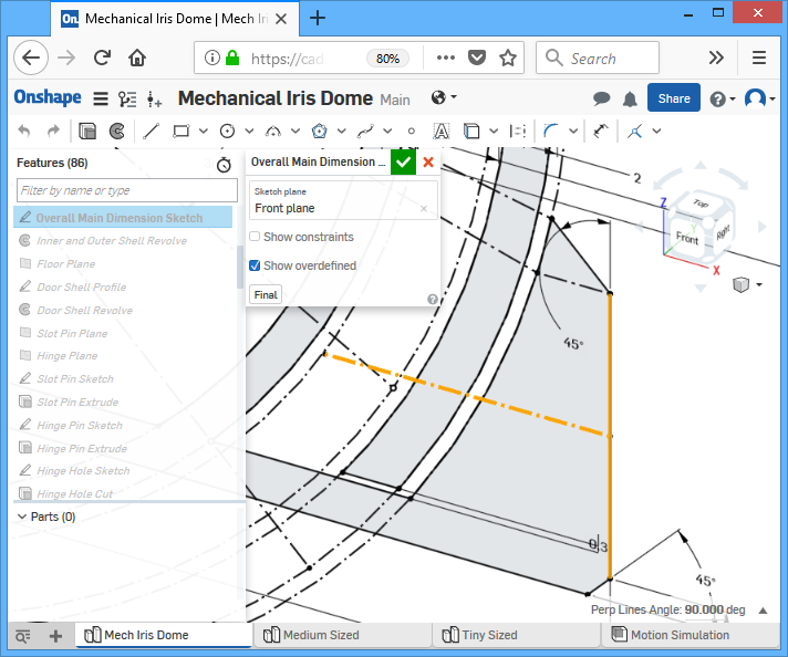
The very first sketch will be one that defines the overall dimensions of all the shells. One change in this sketch and the change will propagate into all subsequent sketches. Construction lines are used to define the curvatures of each shell and solid lines are used to define the actual surfaces of the shells. We want the surface of the shells to follow the curvatures defined by the construction lines so plenty of constraints are used between the solid lines and the construction lines. For the subsequent revolve-extrude operation to work, the solid lines must form enclosed regions to create the cross section.
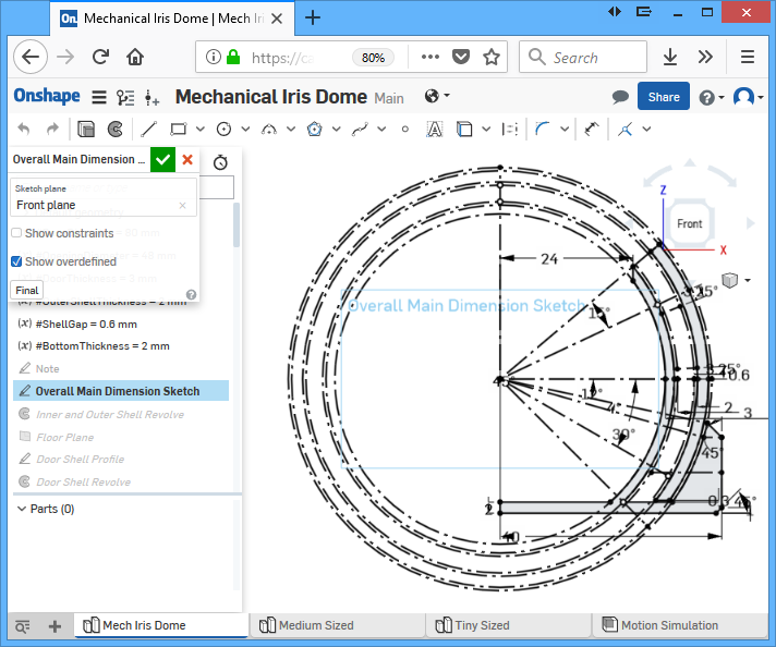
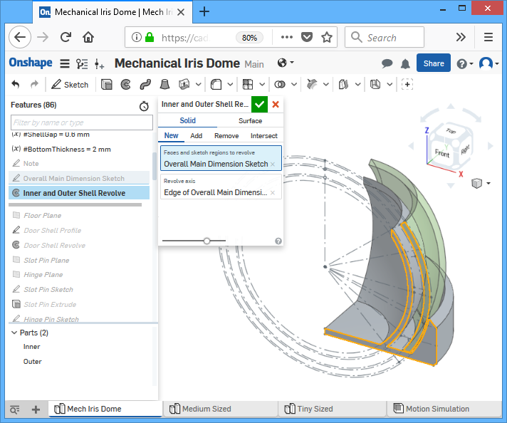
The revolve extrude operation is a full circle rotating about the central axis (defined as a construction line in the sketch). This create two solids, one is the inner shell, the other is the outer shell. The parts are listed in the list of parts (in SolidWorks, this would be in a folder called “solid bodies”).

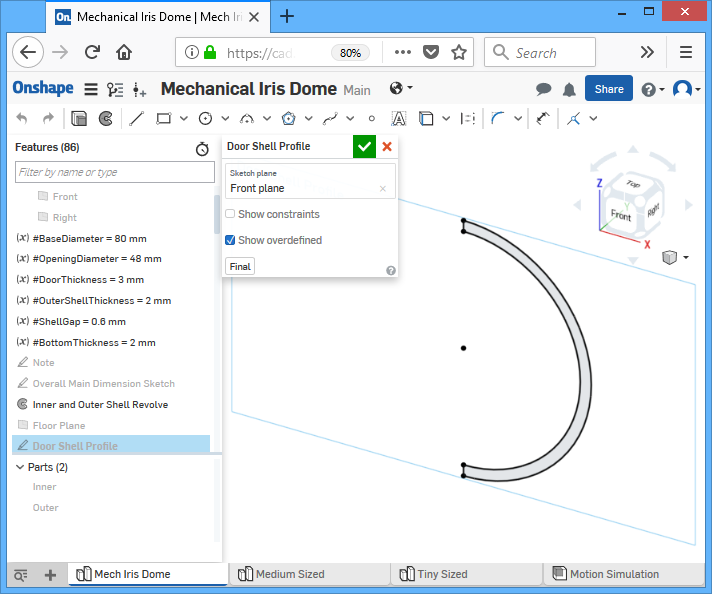
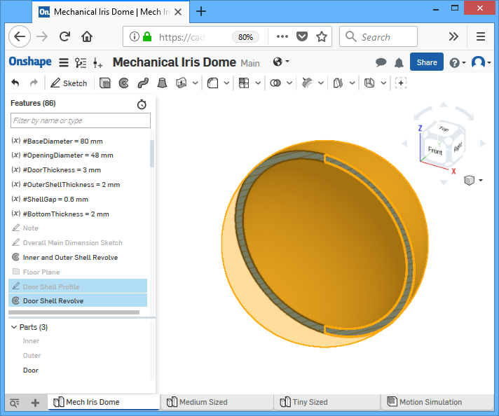
The next sketch simply defines the cross section profile of a hollow sphere. A revolve operation is used to create this hollow sphere. A single door piece will be created from this sphere, so the next couple of operations will cut away parts of this sphere in order to create the shape of the door.
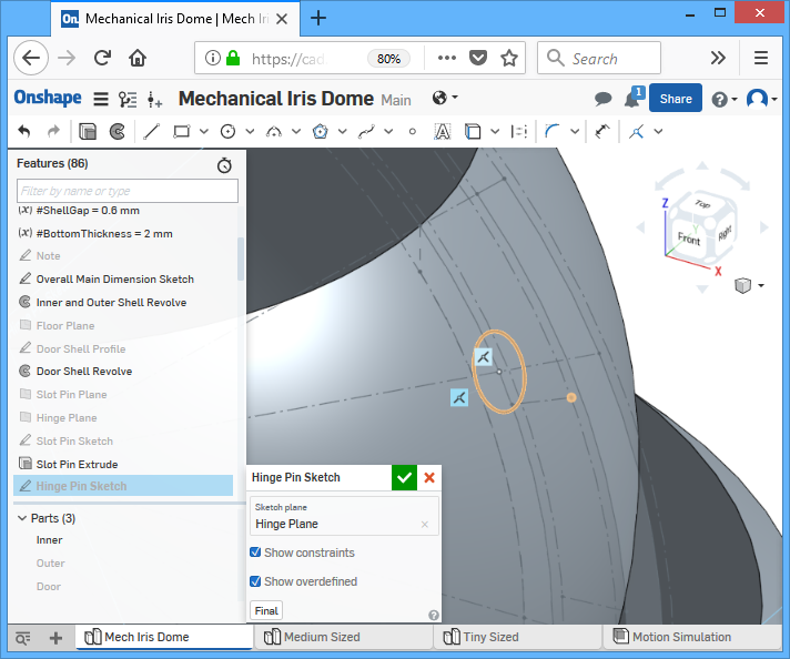
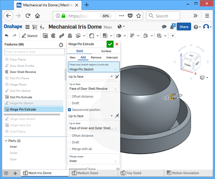
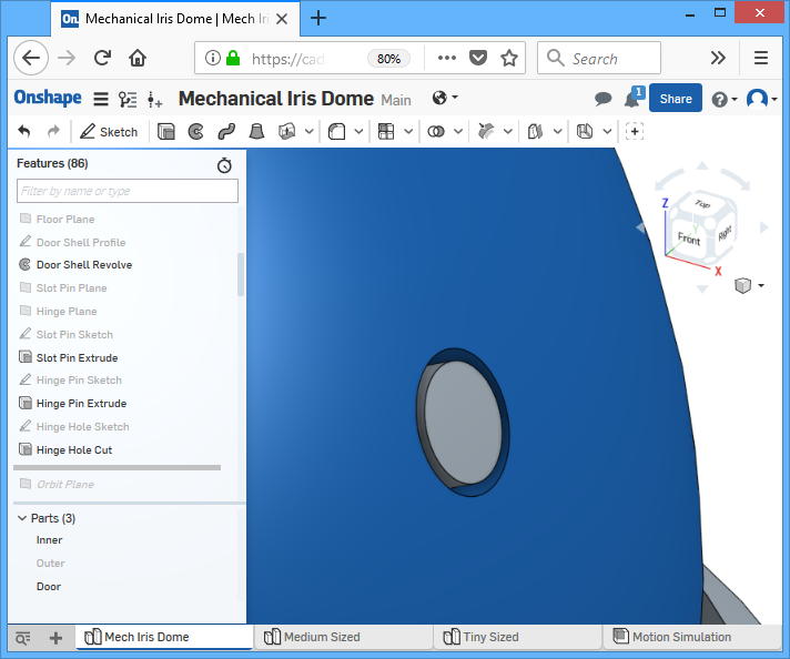
But first, we create the hinge and the hole for the hinge. First, a plane is defined to be on the outward facing surface of the inner shell, normal to the direction of a line that we defined in the very first main sketch. A new sketch is started on this new plane, and all it has is a simple circle, centered on the line I just mentioned. The size of the circle is also defined in the very first main sketch, using angles, not distance, so that the size of the hinge scales correctly if you wish to make the entire model bigger or smaller by changing the variables. This is accomplished by having a constraint between the bottom point of the circle and the appropriate point in the first main sketch. Once the circle is fully defined, we extrude it into the inner shell and also outwards into the door sphere, but ensuring the merge group only contains the inner shell.
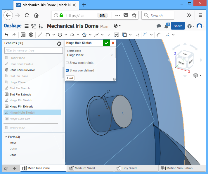
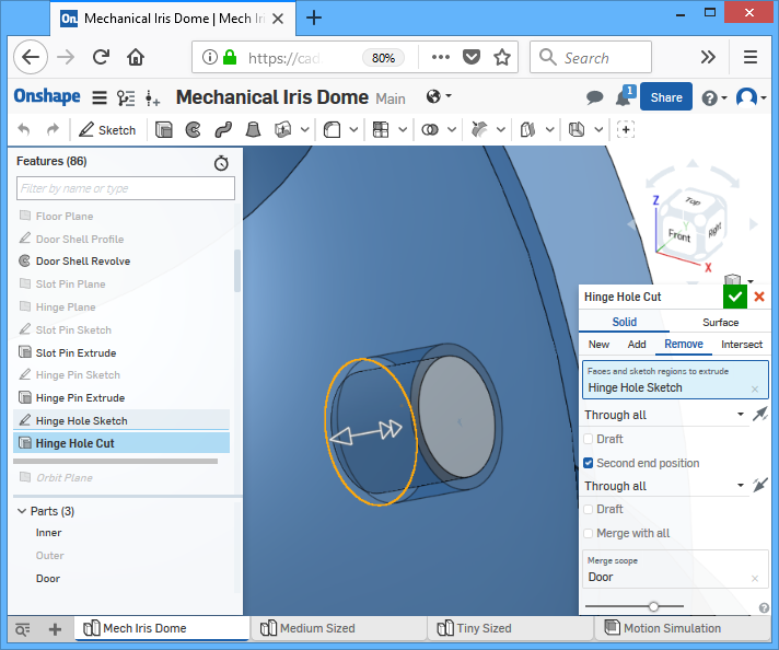
To cut a hole into the door to fit over the hinge, we simply define an offset line to the circle we just made, the offset will be the clearance gap between the hole’s edge and the hinge’s surface. We then use the extrude operation to remove the circle from door sphere (not anything else).
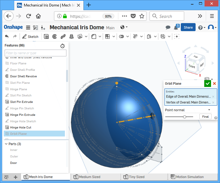
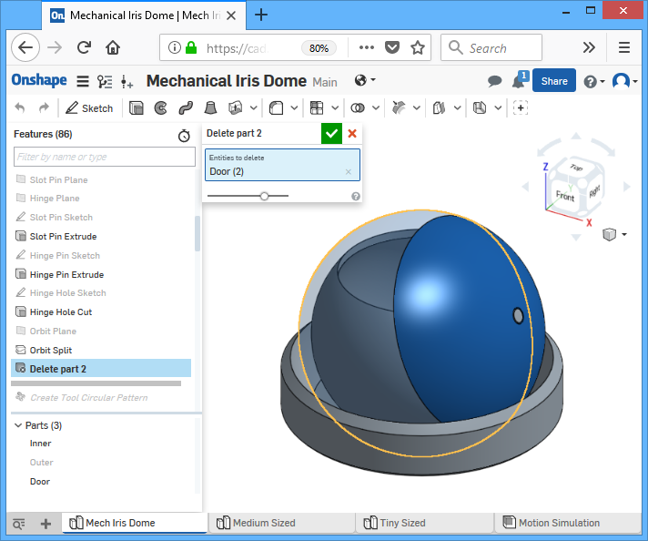
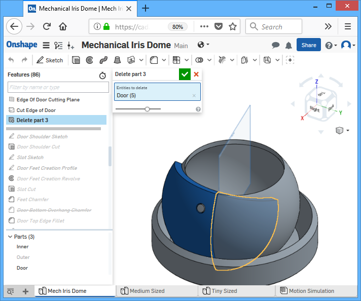
The door will rotate about this hinge axis. The door’s corner will orbit around this axis. In order for the door to close, the door’s corner must meet the top-most point on the sphere. This orbit will be what defines the curvature of the door’s edge. The top of the sphere is already defined in the first main sketch. A “orbital plane” is created to intersect this point and normal to the hinge axis. The door sphere is sliced into two pieces by this orbital plane, and we discard the piece we don’t want with a delete operation. Now the piece we keep should be a half shell that crosses the point I mentioned.
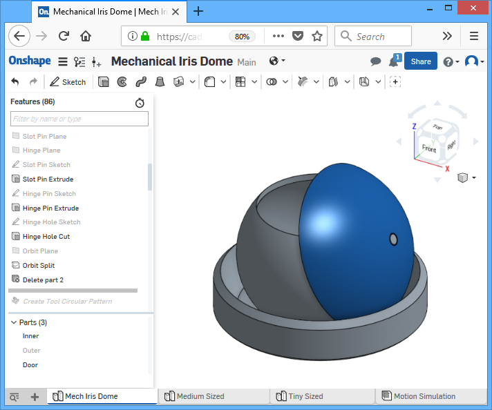
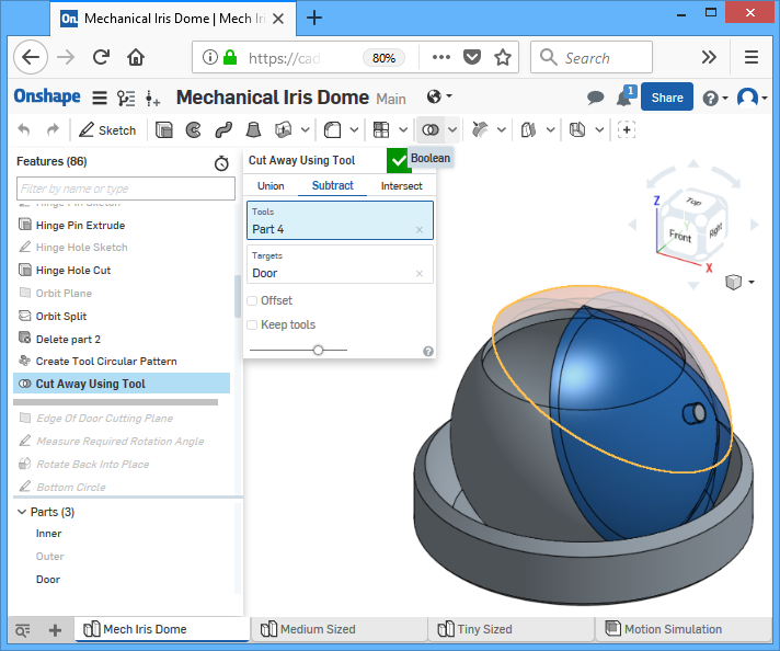
This piece is currently representing just one door in the closed position. In order for more doors to fit into the close position, we need another cut into this piece. The shape of this cut will need to match the shape of another door. So we simply create a copy of the current door piece, and rotate it 90 degrees around the central axis. This creates a second door piece that becomes our “cutting tool”. Using the boolean operation, with the original door piece as the target and the second door piece as the tool, we cut into the original door piece to create the curve, and discard the tool after.

(the more experienced modelers will have noticed that this technique leaves zero tolerance, but realize that the rest of the model has plenty of “slack”, between the shells, around the hinge, etc)
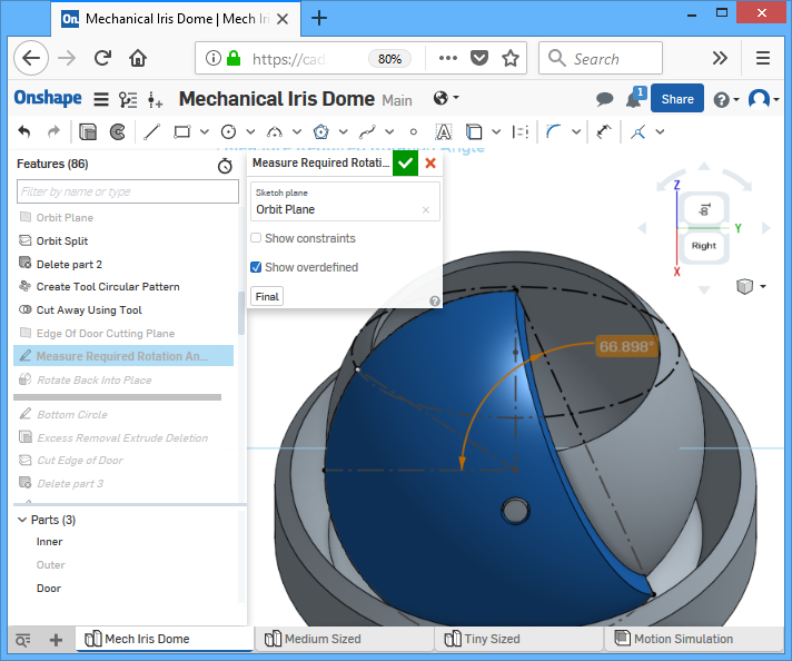
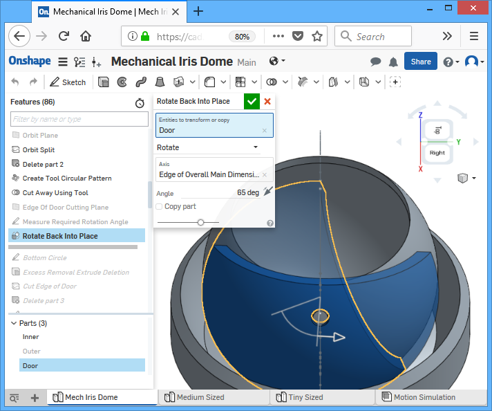
The door is now still in the closed position, and we need it in an open position during the 3D printing, so we rotate it downwards. The angle of rotation can be measured using a sketch on the orbital plane. Onshape does not have the ability to automatically perform the rotation linked to this measurement, so the rotation angle has to be a manual input.
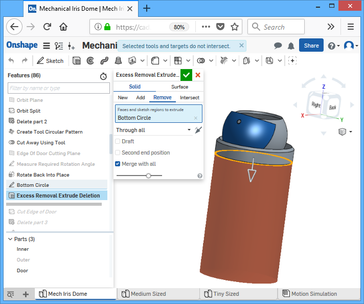
The “excess removal extrude deletion” feature simply ensures that none of the door protrudes below the bottom of the model. With the dimensions currently specified, it actually does nothing. But it is a good idea to keep it there in case you modify the geometry in such a way that it’s required.
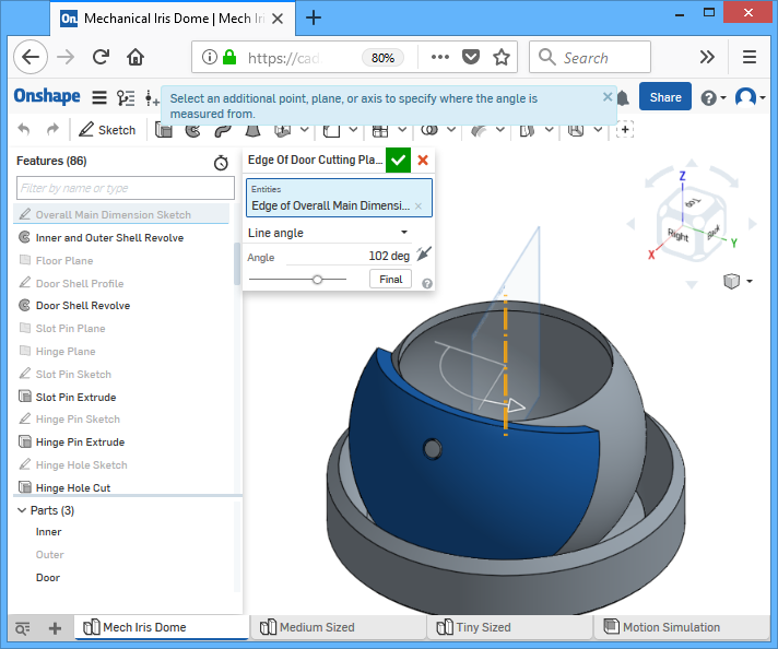
The door is still too big, the “right” side of it needs to be cut away. This is done by defining a cutting plane at an angle, slicing the door with the cutting plane, and then deleting the unwanted piece.

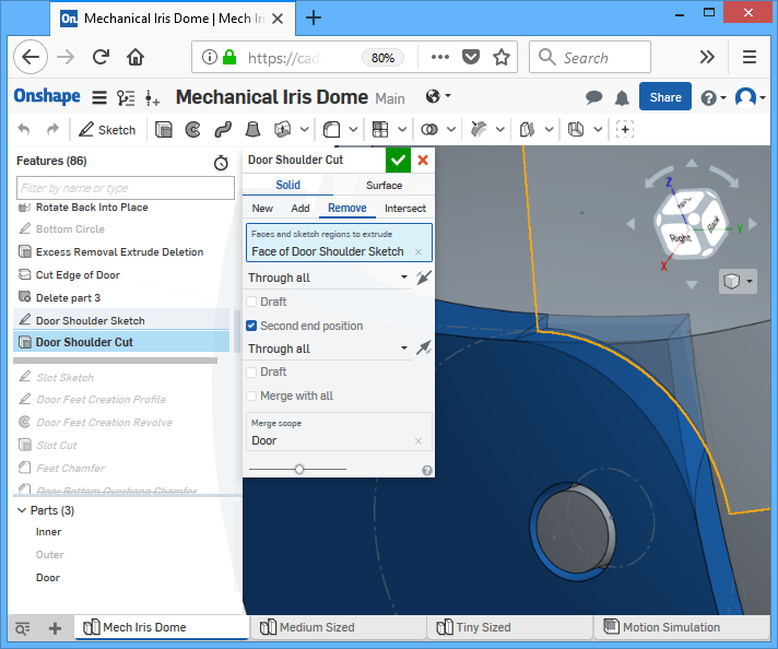
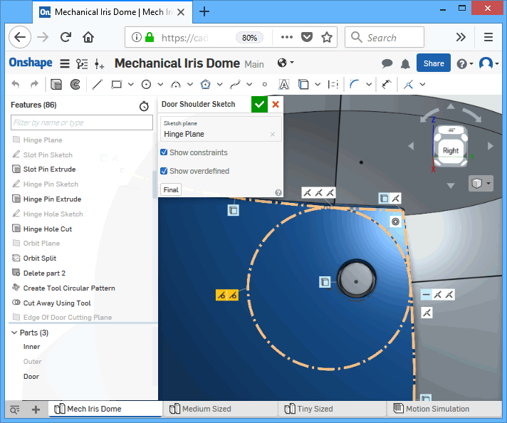
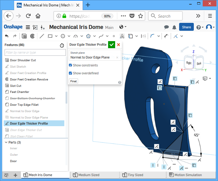
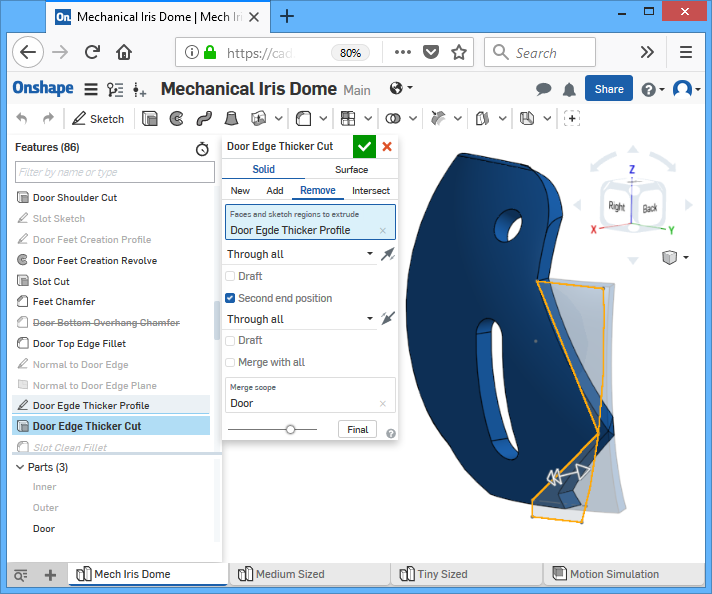
The door has a sharp corner around the hinge. We’ll call this the door’s shoulder. It needs to be round so that the adjacent door piece does it hit it. Although a fillet operation can solve this problem, it’s difficult to calculate a parametric fillet dimension. Instead, a cutting profile sketch is used with a circle that is tangent to the door’s edges, this accomplishes a fillet that resizes well with the model as other dimensions are changed.
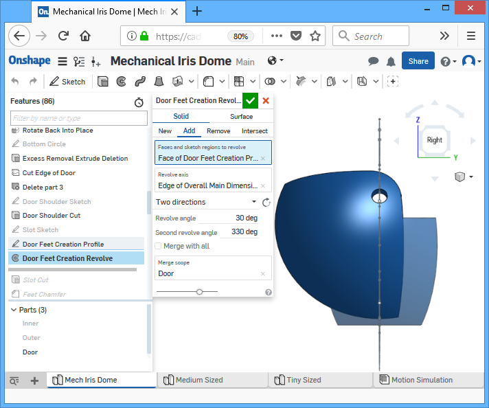
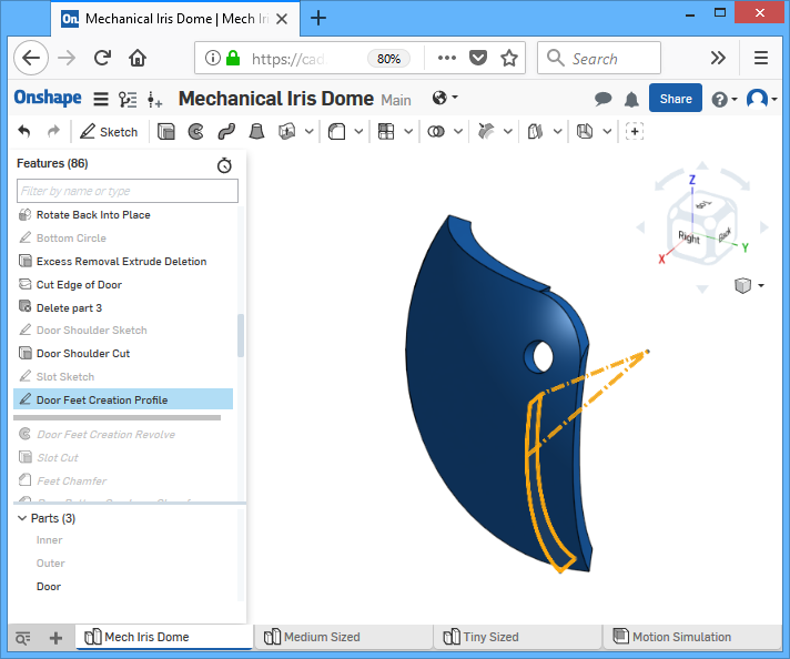
The door does not touch the floor right now. We need it to touch the floor, as I explained much earlier, the feet (bottom) of the doors are glued to the 3D printer’s build platform so it holds steady during the print. A revolve profile is drawn on XZ plane and then revolve-extruded towards both the left and right. The size of this profile is constrained to the midpoint between the hinge and slot (hence why the slot sketch was earlier in the feature list). The portion towards the left extends the foot’s size and gets rid of a lot of unprintable overhangs of the rounded door edge. The portion towards the right adds strength to the plastic during the printing process, that area will become weak because a slot will be cut near there, so we need the extra plastic.
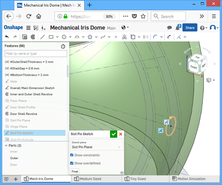
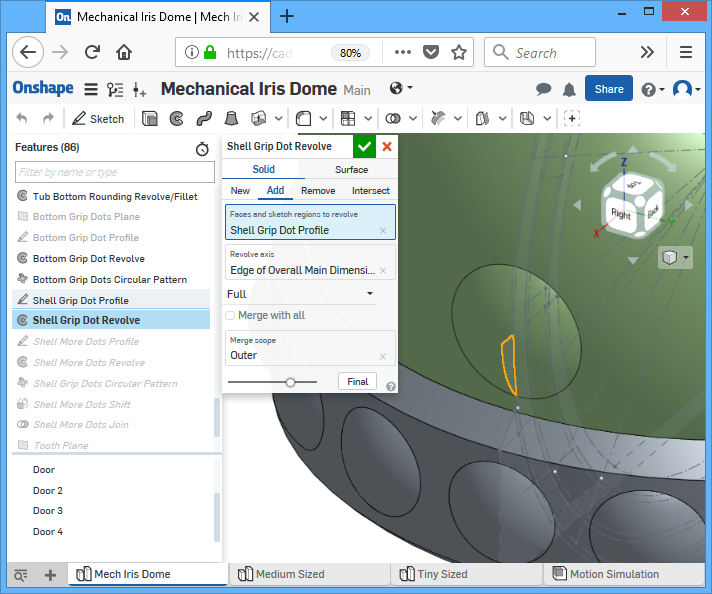
We still haven’t made the pins for the slots yet… This is created similarly to the hinge pin except from the outer piece inwards. Its center is constrainted to the horizontal axis of the first main sketch, and the diameter is constrained to another point in the same first main sketch that is offset by an angle.
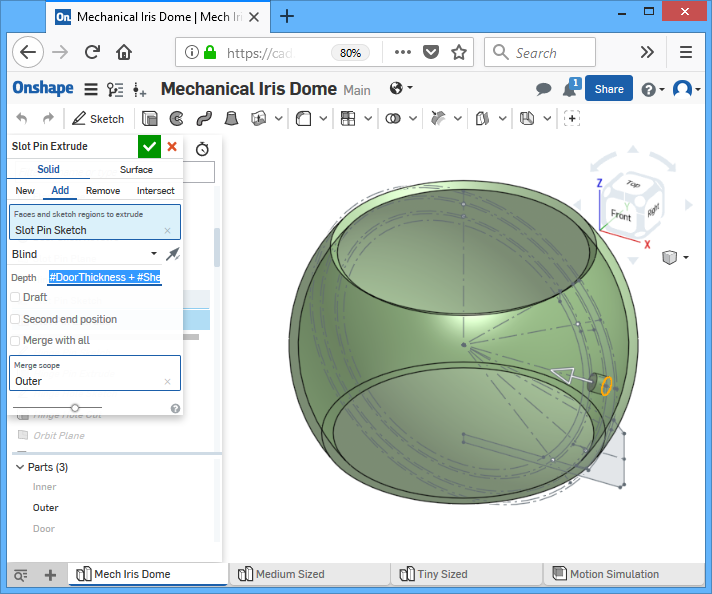
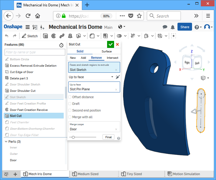
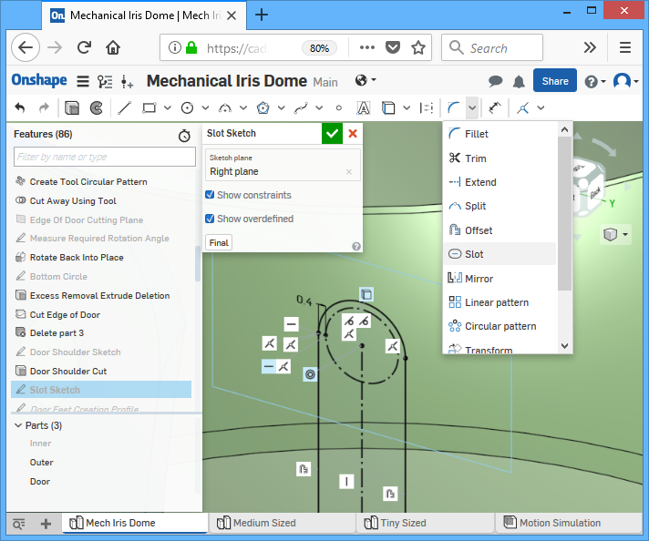
Once all the plastic is there, we cut the slot out. The slot’s width is constrained to the slot pin’s dimensions, with a clearance offset. The length of the slot is kind of estimated, I’m too lazy to math it out so I just made it “long enough” according to the motion simulation.
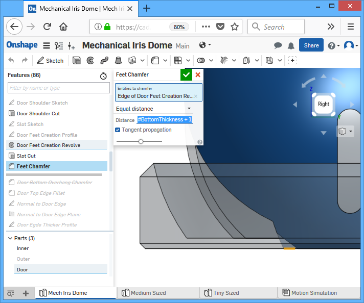
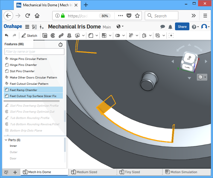
The left side of the door foot is given a chamfer angle. This is so that the feet can clear the bottom floor of the inner piece as it swings upwards. Thus, size of the chamfer is defined as an equation linked to the bottom floor’s thickness.
The “strengthening” plastic on the right side of the door are cut with two angles. The bottom angle is simply to make sure that it is 3D-printable (no extreme overhangs). The angle up on top makes sure it doesn’t interfere with the adjacent door.
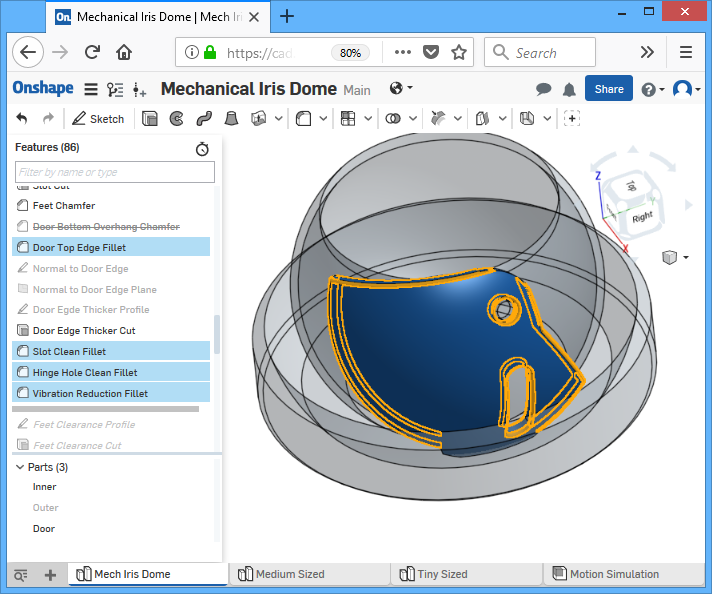
A bunch of different fillets are done around some edges. The door’s visible edges are filleted to look pretty. The side edges, hinge hole, and slot, are filleted so that the printer vibrates less during printing, and to reduce friction from possible 3D printing artifacts (drips, strings, seams). The radius of all these fillets are calculated using a equation linked to the thickness of the door shell, so they always resize properly. (but if the radius is below the printer’s nozzle radius, then they won’t actually have much effect, unfortunately)
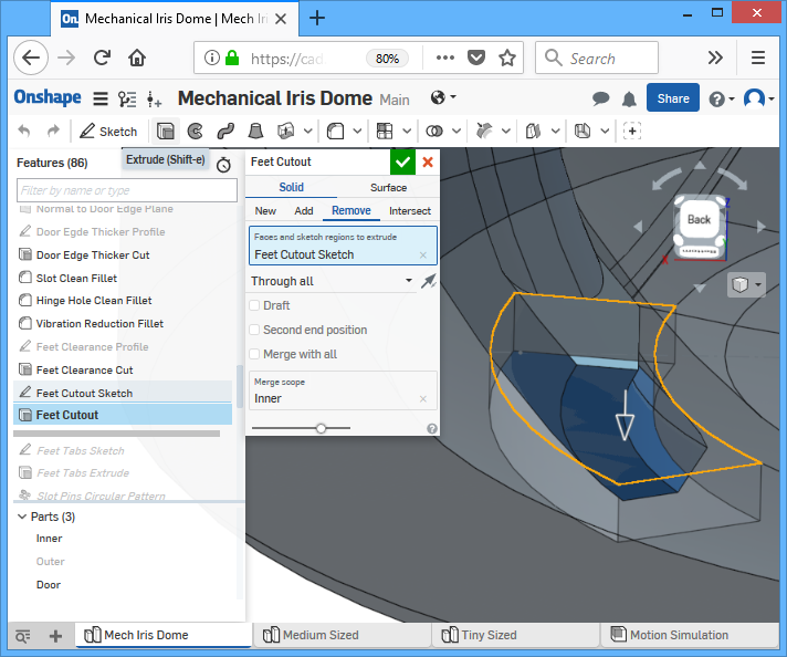
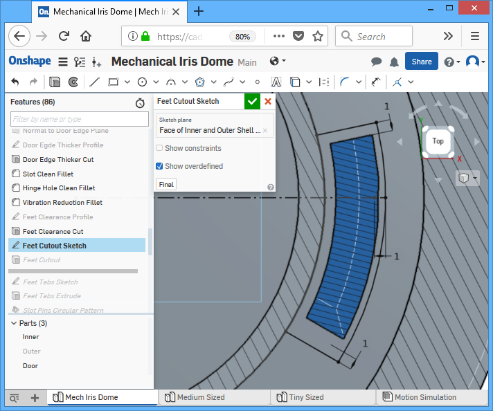
Where the door foot meets the floor, the surface is at an angle. We need to cut out a hole in the bottom of the inner piece so the foot can touch the floor. I do not want any overhangs from this cut so the feet must also be straightened out. This is done using a cut with a circular profile pointing directly upwards.
![]()

Then the hole is cut as well, using constraints to maintain a clearance around the foot. The screenshots don’t show the constraints perfectly so open the document and check where the constraints are actually placed.
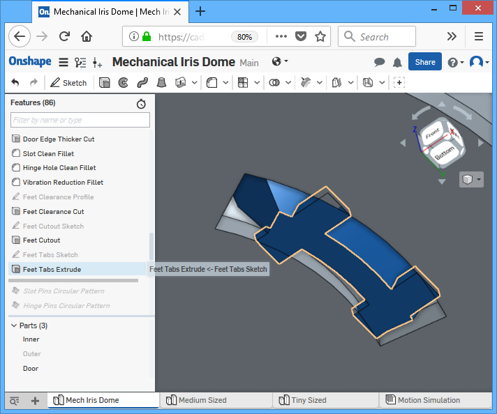
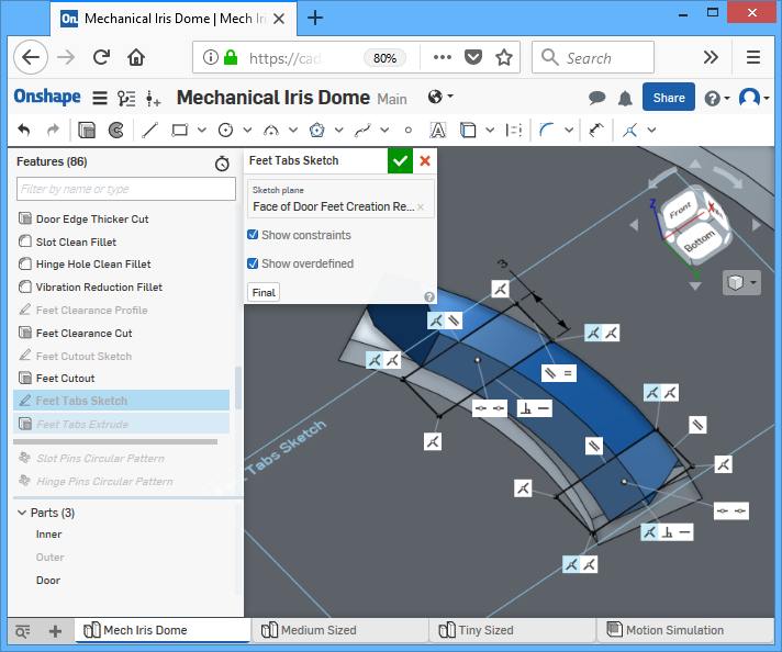
The tabs are given to the foot to join it to the inner piece, but the tabs should be merged with the door only, not the inner piece. This results in overlapping solids, but a slicer (like Cura) doesn’t care. The sketch for these tabs are done really lazily but still ensure that they resize properly and will always be at the two ends of the foot. The thickness should be just thick enough to hold the door steady while it’s printing, but thin enough to be easy to cut by whatever cutting tool you choose.
We need four doors, four hinges, four slot pins, and four floor holes. A bunch of circular patterns are used to create these.
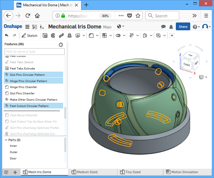
Note: Onshape’s circular pattern tool does not handle chamfers and fillets very well. So now we add some fillets and chamfers to the pins. A large chamfer is done near the foot to give it extra swinging clearance. The smaller top surface chamfers are there to ensure the 3D printer doesn’t leave any infill-to-wall gaps.
Note: if you are using a CAD tool that handles fillet and chamfer circular patterns better, then these fillets and chamfers should be done before the pattern. This flaw in Onshapes makes it difficult to adjust the number of doors in this toy. Thus, the chamfers in the following screenshots should be done to all eight pins, not just the original.

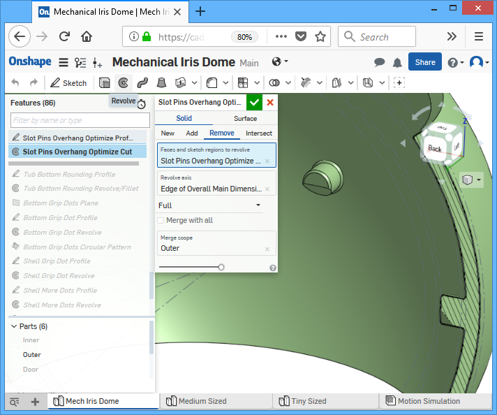
Now that all the slot pins are created, I wanted to make it more printable by removing as much of the overhang as possible. This is done with an angled revolve cut, revolving about the central axis.

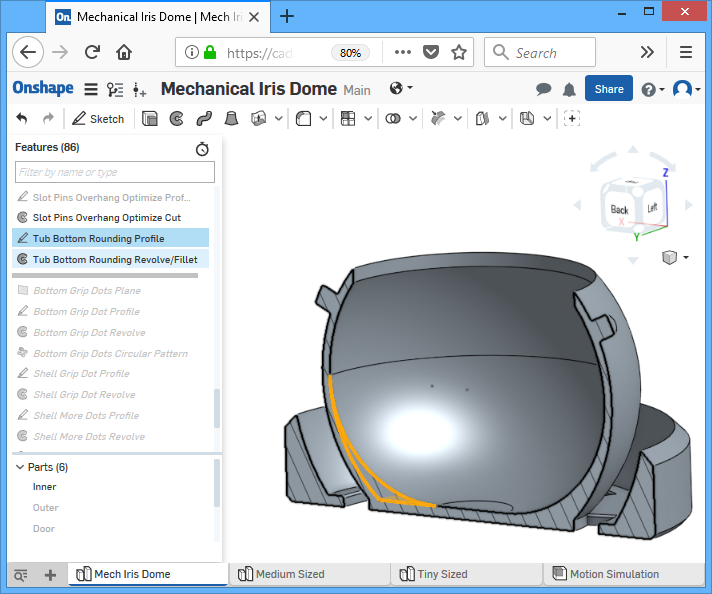
The inside of the tub is rounded out with a revolve-extrude operation. The profile sketch defines a curve that is tangential to the bottom and the side, and also incident to where the tub wall is vertical. This could’ve been done with a fillet operation too but it would’ve involved an equation that I was too lazy to figure out.

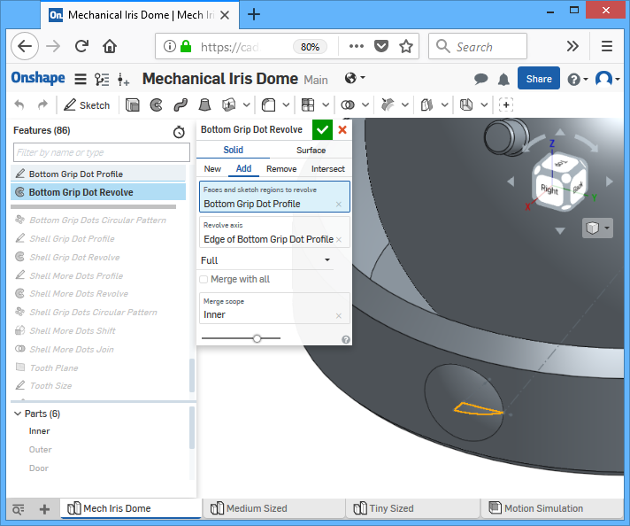
Now we add some dots to the bottom piece. This is actually kinda complicated. I wanted the dots to resize properly as the whole model resizes, so the first thing to do was to figure out the height of that vertical wall. That was done in the first main sketch, and another construction line was created with the same length using a length-equal constraint. This line was also constrained to the midpoint of that wall. A plane is created with that line so it is also at the midpoint of that wall and parallel to the floor (this is better than a vertical plane because it allows the dot to “hug” the curve without mistakes). A sketch for the dot profile started on that plane and a midpoint constraint is used on that construction line so that the radius of the dot will be just smaller than half of the wall’s height. A revolve-extrude is done on that profile sketch and then the created dot is circularly patterned all the way around.


The dots on the outer piece is created similarly, with less attention paid to size except it cannot exceed the lip of the bottom piece. The profile is defined on the default vertical plane for convenience, it hugs the outer shell and is guaranteed to generate without sticking out in unexpected places.
The “bulge” size of all of these dots are set to be automatically proportional to the overall size of the model.
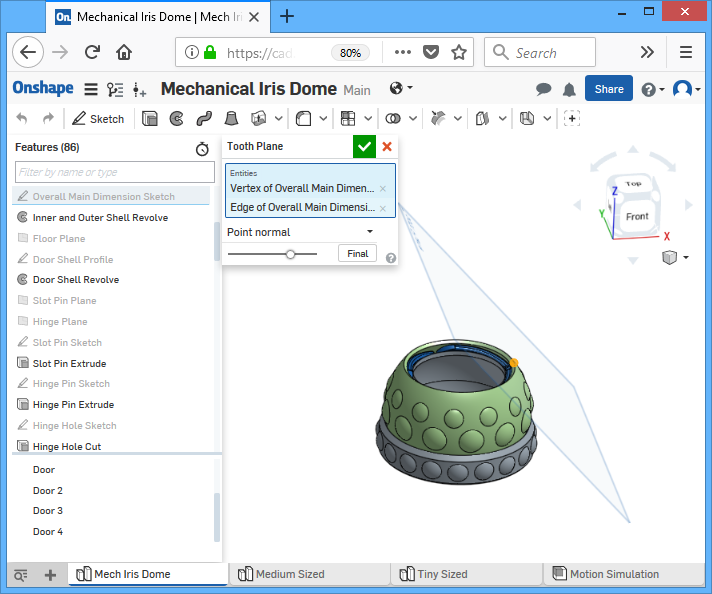
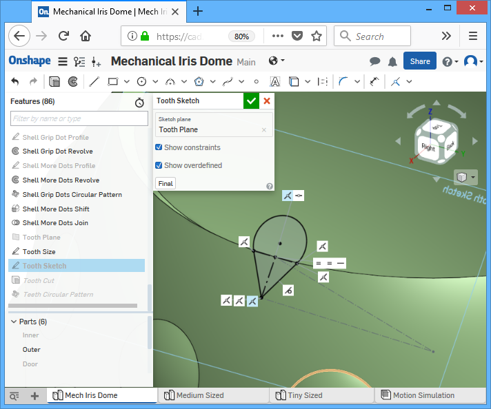
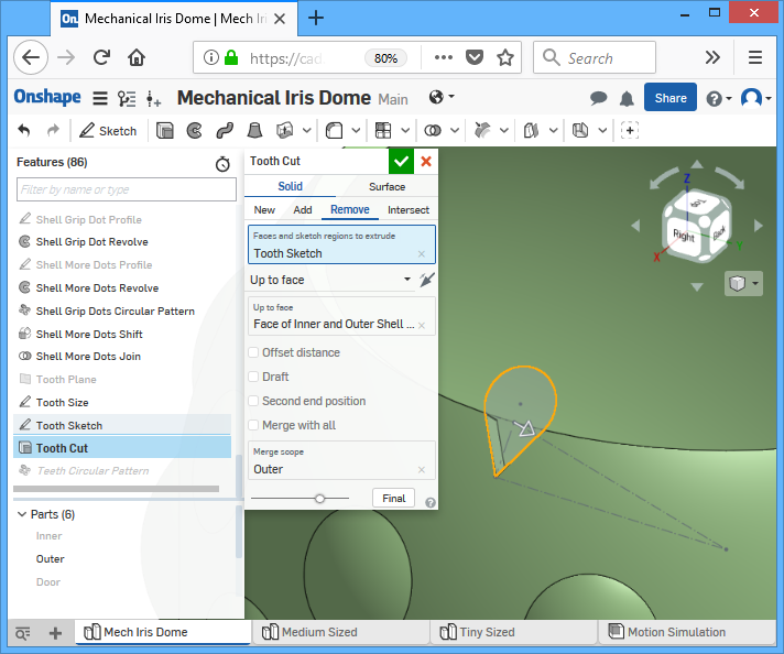
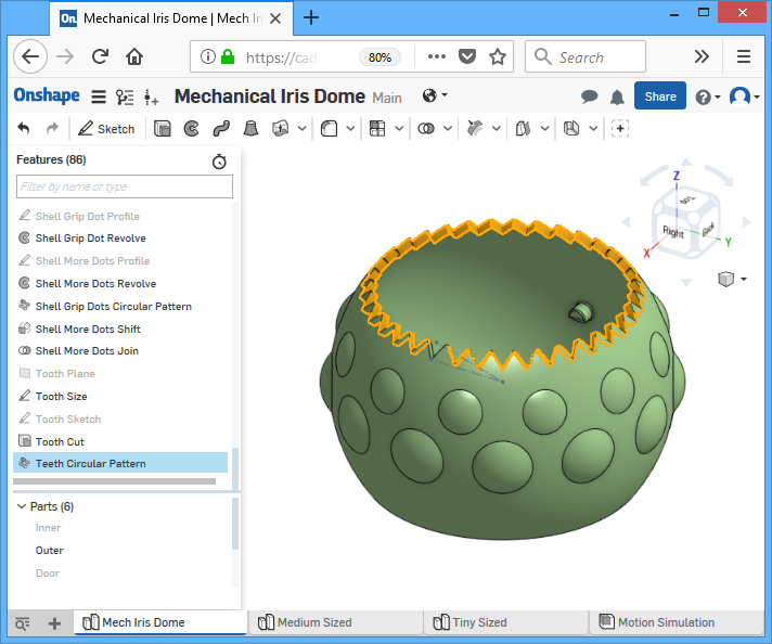
Then we get to the teeth, which is a single cut that is circularly patterned. Start off by creating a sketch plane normal and tangential to the edge of the opening. The size of the tooth is determined on another default horizontal plane using an angle. On the sketch plane, draw an isosceles triangle (using equal-length constraints) and use a incident constraint so it matches the size we defined. The circular part of the sketch is to ensure that it cuts more than we need to, and do not leave behind anything microscopic in the model. A cut is done using extrude-remove towards the inner face of that shell.

We are done, kind of…
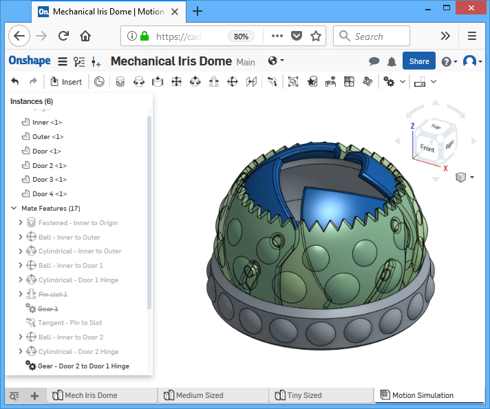
Now we can make an assembly, which means we can define how the pieces move, so that we can simulate how the doors open and close. I’ve named all of the mates inside with the type of mate followed by the relationships, this will make it easy for you to identify them. Also, you can open the document and explorer it yourself, remembering to use your mouse over parts to view what comes up highlighted.
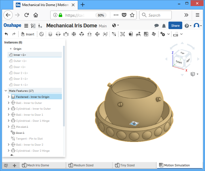
First start by creating an assembly, then placing the inner piece inside. Do not place all parts inside at once, do it one at a time. The inner piece is constrained to the “world” by using a “fixed” mate with the origin point.
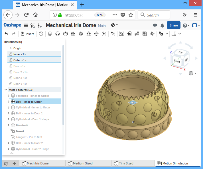
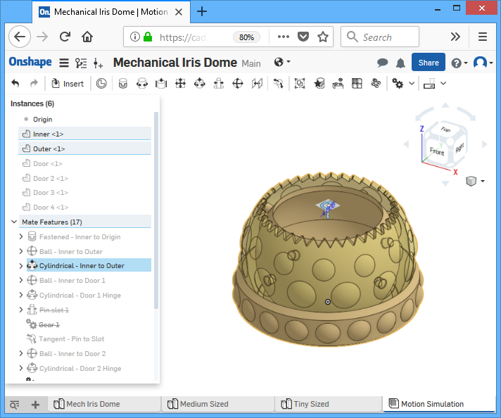
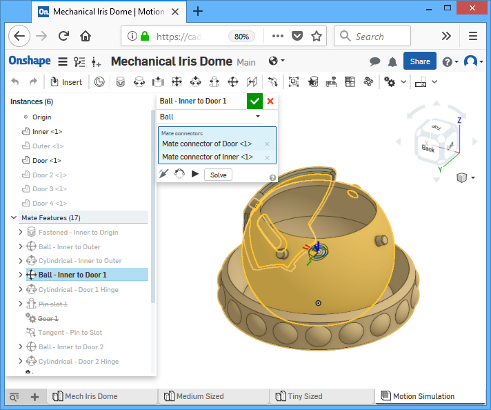
The inner piece and outer piece are joined together by two mates, one is a ball mate which makes sure the two sphere centers are always coincident. The second mate is a cylindrical mate so they can rotate on only the vertical axis.
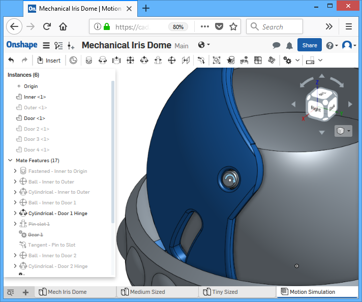
The first door is inserted, and using a ball mate to join it to the inner piece for alignment. Then the hinge is given a cylindrical mate so the door only rotates on the hinge axis.
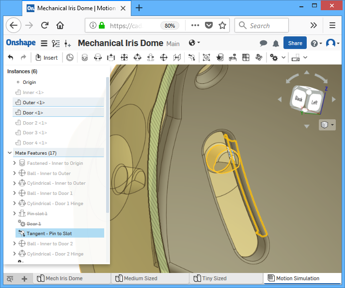
Then the edge of the slot is given a tangential mate with the slot pin of the outer piece, this is the key to creating the proper motion. (I’ve also tried the slot mate, which didn’t work because Onshape didn’t recognize it as a slot, and I’ve tried a gear mate, but it didn’t end up being a real simulation)
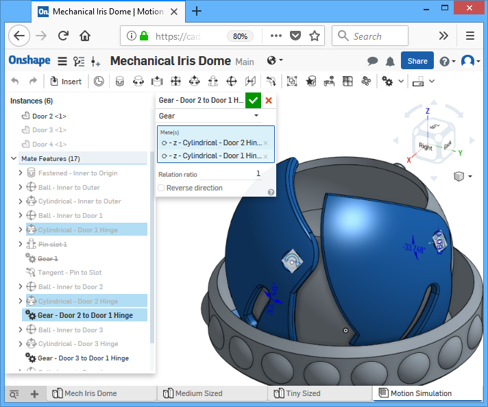
The rest of the doors are placed, all with the same ball mate and cylindrical mate, but not with the same tangential mate. Instead, a gear relationship is done between all of the cylindrical mate so they rotate together virtually. This is because I found it annoying to make tangential mates.
We are done, drag the outer piece around to make the doors open and close.
Happy Holidays!
Thanks for the tutorial, it is very nicely done. I am trying to make one with 5 flaps but the pin configuration needs to be changed. Have you ever done one like that?
I really like your design, and the tutorial was very well written. Which one of these would be a good size to store SD cards in, in your personal opinion?
The medium sized one is fine for if you just want to dump in a bunch of cards, but if you are looking for a particular card, you’d have to dump them all out first. The large size one could let you put in many cards standing up, I would print another insert with slots to do that.
Double check with the 3D model.
Printed the large one. Cut the tabs, everything looks perfect but I cant twist the top half to close it. Its stuck solid. I printed with PETG on an MK3S
Great post. Thanks for sharing all the design details. I’ve been using solidworks at work, and recently discovered onshape as well. Good to see someone else also using it.