I am building a quadcopter using a FrSky Taranis X9D radio. It came with a FrSky X8R receiver. I wanted to keep my wiring clean by using the S.BUS feature on the FrSky receivers, I purchased a smaller FrSky X4R-SB receiver. The X8R has 8 PWM channel pins and the X4R-SB has 3 PWM channel pins, but if I use S.BUS (which is serial, not PWM), I can access 16 channels using only 1 pin, on both X8R and X4R-SB. The X4R-SB is much smaller, making it more ideal. (do not confuse the X4R-SB with the D4R-II, this is important, D4R-II uses CPPM, not S.BUS)
(update 10/25/2014: a follow up hack for Smart Port)
I want to use a Naze32 flight controller, which is open source and does have code to interpret S.BUS protocol. S.BUS is UART communication but it is inverted and the Naze32’s UART cannot accept inverted input. Some flight controllers, such as the Pixhawk, has a dedicated inverter just to solve this problem, but the Naze32 does not.
The first option is to buy a “S.BUS to CPPM converter” but CPPM is not a serial bus like S.BUS and thus does not have the advantages of being a serial bus. CPPM uses timing, timing needs to be measured (measuring things = possible error) and the signal edges can be affected by capacitance, noise, etc. Also having such a converter means there will be a tiny bit more latency in the system. These two disadvantages are probably too insignificant to notice performance wise. But I still didn’t want to spend another $13 + tax + shipping just to solve a problem that shouldn’t have existed in the first place.
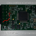
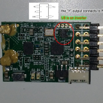
The second solution is to buy an “inverter cable” which is a cable that has a NOT gate inline and then shrink wrapped. Or I can just buy a NOT gate and make the cable myself. I still didn’t want to spend the money. I opted to hunt down the inverter on the X4R-SB circuit instead, and connect a wire to the input of the inverter (labelled as “A” in the datasheet). This provides me access to the un-inverted signal that I can directly connect to the Naze32.
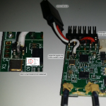
See the pictures below to understand how this hack was done.
And just in case I confused you even more, all you need to do is connect a wire to the “A” pin.
I have tested it with Naze32 Rev5 and firmware f4d556c68876ccd5902bddf1cade32f1bb382c9f. Works like a charm.
It is probably possible to perform the same hack on a X8R but the X8R is constructed using two PCBs and the inverter is covered up by one of them. Separating the two PCBs is very difficult and risky.
The Smart Port (I think it’s also called S.PORT) is another inverted serial bus available on the X4R-SB and X8R but it is bidirectional. Since whatever you want to connect to it will need a bidirectional circuit anyways, it is not worth it to perform another surgery on the Smart Port. Also, the Naze32 can use SoftSerial to transmit in an inverted fashion, so a dedicated inverter isn’t even required. (SoftSerial would not work well for taking inputs, but outputs is OK)


Frank, hi!
pls help – on 1 picture the red circle?
All you need to do is connect a wire to the “A” pin. That’s all you have to do. I swear it’s that simple.
Thanks!!! 🙂 really simply:))) next –> smart port
Already done, see next blog post
So just soldering the A pin 😉 Yep, works great, thanks!
Its much smaller in real life then on your pics.
Wow this is so simple, thanks. So let me ask this does not change the operation of the S.Bus connection to other devices that have an inverter in place, such as a DJI Nasa flight controller, right?
If you do this hack, then it will NOT work with DJI Naza, it will NOT work with Pixhawk.
I forgot to ask, does both BaseFlight and CleanFlight support S.Bus? What version do I need to support the S.Bus connection. This should work on other Naze type boards like the Flip series, right? How about the Naze32 mini?
It should work with Flip32 and Naze32 mini
Bad weather these days, I haven’t done much multirotor stuff lately, I haven’t updated the firmwares to the latest github commits. I also can’t test to confirm. But I think my github account has working copies for both BaseFlight and CleanFlight.
Hi
I have just reciever a fr sky TFR4 SB fast compatible rx.
Can a mod be don on this rx to invert the sbus signal.
Thanks for your info
My answer is “probably”, because I have not seen the circuit in person.
You can find out yourself without too much risk.
Hi,
Thanks for publishing this info. I’ve done this “hack” but I’ve used one of the 4 pads next to the inverter. A lot easier to solder.
I’ve got it working with an afromini32 (micro naze32). But I’m not sure if I should add a resistor between the X4R and the afromini32. Any thoughts ?
Thanks again for sharing.
a small resistor will be a good idea, a current limit so that you won’t accidentally burn out a pin
Thank you Frank for the great hack! And thanks to the hint from Martijn, I used the handy through-holes right next to the inverter to mount a small header.
http://forum.autoquad.org/viewtopic.php?f=33&t=4256
Thanks again,
-Max
OK I think I understand what is being accomplished here, but to clarify. If I make this mod to my X4R RX, I will then have access to 4 PWM channels on the RX plus the remaining 12 channels via the new S-Bus connector, right?
Correct. Also note that the S.BUS connector provides 16 channels those 4 first channels are included. You will not need to connect the 4 PWM channels at all.
On the X4R-SB you already have S-Bus on one of the sets of pins. This hack is simply to get the same S-Bus output but not inverted (useful for some flight controllers). The X4R-SB only has channels 1-3 via PWM. There is another X4R version that has 4 PWM channels and no S-Bus (unless you hack it 🙂 ).
-Max
Hi,
There might be a good reason, but indeed why not use the through hole if they are equivalent . It should be easier than the U8 pins to solder ?
Thx
How can I get telemetry? Right now I just need Vbat. I have the Taranis Plus, Naze32full and X8r.
–Thank you–
T.Williams, Oklahoma City, USA
I posted about telemetry in another blog post
If I solder a wire to A on the inverter, which pin do I then connect to on the naze?
So I’m a little bit confused here… what is the A connection providing? Cppm? or PWM Ch.4? Thanks for any help!
S.BUS is not CPPM or PWM, S.BUS is a serial protocol with a non-standard baud rate.
“A” and “Y” are the same, except “A” has standard serial signaling and “Y” is always equal to the inverted “A”.
Oh, I see now, thanks!
where to I then connect to my board, standard rx or uart? and what pins?
Please read the Naze32 instruction manual for this.
hi bro, just need to know, for the X8R receiver with Naze32, is there any method like you modify above will allow Naze32 using all 16 channel in Naze32? i was little confiused with your explaination… can you elaborate a bit please? thanks.
-AhLee
It’s the same hack, but harder on the X8R receiver. The components are more hidden because the X8R is built with two circuit boards stacked together. I suggest buying a X4R-SB instead, because it is easier to hack and you won’t break a X8R if you screw up.
As a suggestion, why not just solder away U8 and put a cable between the A and Y instead. Then you have left R25 as current limiter
You are right. Now I am wondering why I didn’t do that in the first place… This was months ago… I agree that I should have done it your way, but my way does have the advantage of keeping the inverted version of the signal.
I tried this mod to x8r
and success! thx!
I upload on this mod (it’s Korean, just see video)
and.. it’s hard.. no recommend in x8r
if you have x8r, buy inverter cable
Its actually really easy on the x8r and x6r. Here is how.
Remove your receiver from the plastic case. Place it so the bind button is facing up and the smart port is closest to you. Just above and to the left of the smart port there are 4 open holes starting at the bottom one go up one two three to the third hone and solder in a wire. That will be the uninverted signal. No need to spit the two boards at all.
Here are some photos the first on is what you see if you separate the two board. the second is where you should make the connection without taking them apart.
https://drive.google.com/file/d/0B6ByTAAB61Gbbkd3bXhvUE4xZVk/view?usp=sharing
https://drive.google.com/file/d/0B6ByTAAB61GbUUU0dEFHSmxteG8/view?usp=sharing
I tried this mod to x8r
and success! thx!
I upload on my blog this mod (it’s Korean, just see video)
and.. it’s hard.. no recommend in x8r
if you have x8r, buy inverter cable
Actually, its much easier to do with the x8r, just flip it over and connect to the third pin of “P2”!
http://imgur.com/S7R42nc
Chris,
Do you have any more info on this modification please?
After the mod is done what should the settings be under ports and configuration on the naze32
rx_ serial or rx_ppm etc.
Thanks a bunch
Thanks for this mod:)
What do i have to set in the Naze? PPM or SBus?
Thank you, Wieland
This is great. Have you thought about removing the inverter entirely and just bridging pin A to Y for a cleaner hack or is too difficult?
So which is the easiest way to hack the inverter on the X8R, I have one coming in the next few days and would like to use sbus to the Naze32
How daft, the xy are meant to be bridged for reverse Sbus, this is not a hack it’s a standard setting on the X4, but I cannot see how it can be done on the X8, so all in all a waste of time and effort.
Sorry, I’m having some trouble…
Sbus works, but the naze32 only reads my sticks… Any idea what I am doing wrong?
Naze32 rev 5
X8r hacked
Taranis plus
D16 1-16
Axel,
I’m having the same problem too, my quad just read my sticks but it does not acknowledge the RX is there, sending out Lost Signal alarm.
Any idea?