

Connecting More Parts
Using a Breadboard
A solderless breadboard is a type of circuit board that does not require soldering, instead, you simply plug in wires and components into it. You can also take the components out really easily. This all means that breadboards makes it easy to fix any mistakes.
(using a breadboard also means your circuit will break if you drop it, since the components can pop out easily)
Breadboards have rows of female sockets that are already connected together for you. Each row usually has 5 pin sockets. This means if you plug something into one pin socket, you can make 4 more connections to it. In the picture below, you see what a breadboard looks like on the bottom, it has rows of metal clips that your wires will squeeze into, it's the clips that make the connections.


You need wires to plug into breadboards. Sometimes you can just buy "breadboard jumper wires" from somewhere, otherwise, you could buy a big roll of 22 AWG solid core wire, and cut it yourself. Do not use stranded core wire.
(AWG is sometimes known just as gauge, it means the size of the wire, higher gauge means thinner wire, lower gauge means thicker wire. A 22 gauge wire is thicker than a 30 guage wire.)

Availble Connections on the Robot
The robot's circuit board has huge female pin socket headers around the Arduino Nano. This allows you to connect additional wires to the robot and to the Arduino Nano.
There are pins for GND (remember our circuit class, GND means ground, and is at 0 volts), for battery voltage (about 6 volts and not regulated), and for a steady 5 volts (from the voltage regulator).
Every pin from the Arduino Nano can be connected to. But keep in mind that some of these pins already have something connected already, such as a sensor, LED, etc. While sometimes it is OK to share one pin for two connections, you need to think about the design before sharing a pin. For now, try to use only the unconnected pins for experiments.
Below is a diagram with all the pins of the headers labelled with their general function and what they can be used for

For even more detail, go back to the circuit basics lesson and then look at the complete schematic, where all the signals are labelled.
Simple LED Exercise
Use the breadboard to make a LED light up. All you need to do is use a LED, a 220Ω resistor, and some wires. We will connect the LED in series with the resistor and power it with the regulated 5V power supply. The LED should glow.


Infrared Remote Control
We can make your robot remote controlled by any TV remote. If you have attended the classes, I have given you a little device that is the infrared remote receiver (part number is PY-1030A-2). Now we will connect it to your robot and teach you how to make your robot read commands from your TV remote.
Each sensor has three pins, one for 5V power, one for ground, and one for the data output. (I know this because I read the part datasheet)

The PY-1030A-2 is cheap, there are other ones you can buy, but if you do use another one, the pin functions will not be the same as the PY-1030A-2.

We already know how to connect the VCC pin to 5V, and how to connect the GND pin to the ground of the robot. The data pin should be connected to the Arduino pin D8. (D8 is free to use, and it can measure pulses very precisely)

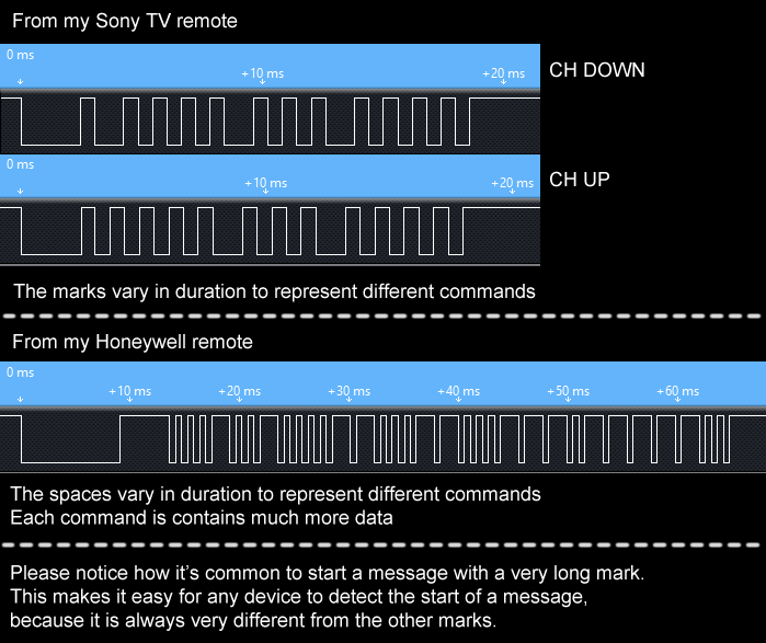
How do TV remotes work?
TV remotes work by sending pulses of IR light. IR light is chosen because people cannot see it. But your light bulbs in your home, the sun, and many other things also output IR light, so how does your TV know which IR light is coming from the remote control?
The IR light from a remote control blinks very fast (pulsing), about 38000 times per second, we call this 38000 Hz, or 38 kHz. The sun doesn't blink at all. The IR remote receiver is a sensor that can detect when IR light is increasing and decreasing repeatedly at about 38 kHz. This is known as modulation (transmitting pulses) and demodulation (receiving the pulses).
The receiver's data pin will output a low voltage signal when the pulses are being detected, and vice versa, it will output a high voltage signal when pulses are not detected (or when the pulses are too slow or too fast, it has to be close to 38 kHz). In the topic of communication, we call the output "mark" (pulses detected) and "space" (no pulses).
Every different combination of marks and spaces means a different command, such as changing the channel on your TV. Sometimes (and not every time), it's not just the order of marks and spaces you need to know, you might need to know the time duration of each mark and space before understanding the command.
The Arduino can read the marks and spaces as low or high voltage on a pin, and translate (decode) the marks and spaces into an integer. The way it does this actually depends on which brand of TV you have, Sony uses a different protocol than Samsung. This code involves a few layers of code:
- detect when there's a signal
- measure the duration length of the pulse
- store the pulse length data into a list
- check which brand of TV using the list (this is kind of complicated)
- decode the list into an integer, according to which TV brand (knowing the brand first makes this much easier, without knowing the brand, it's very hard)
Sounds pretty complicated, luckily for you, somebody has already written an Arduino library to take care of all this. You still need to know what the integer code for each of the buttons on your remote. This is when you need to use the serial monitor to debug what the receiver is sensing after the library has done the decoding.
(if you have followed the previous lesson on Arduino programming, then you already have this library inside your sketchbook)
Exercise: Reading your TV remote
Make your robot move forward when you press "channel-up", and backward when you press "channel-down".

First, you need to know what integer code command is being sent when you press channel-up and when you press channel-down. There's a sketch in your sketchbook called "IrRemoteDebug" (github link), connect the IR remote receiver as shown before, and upload this sketch. Open the serial monitor the upload is complete, point your TV remote at the IR remote receiver, and press the channel-up button. Read and remember the text that appears on the screen. Do the same thing again for the channel-down button.
Second, you need to use your code writing skills. Start writing a new sketch, your logic flow should look like this:

Soldering your IR Remote Receiver
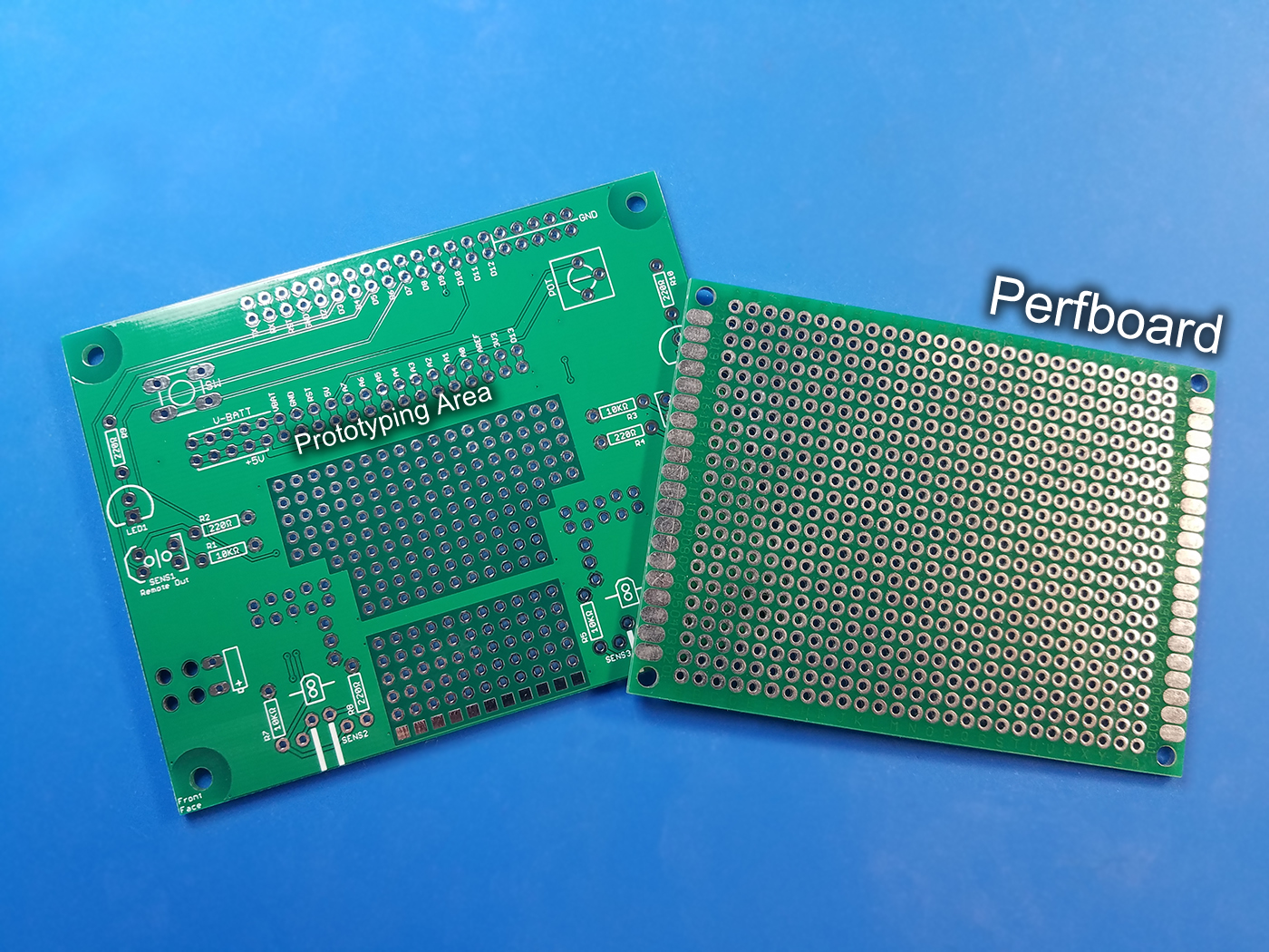
I want to introduce you to another type of circuit board: the perfboard. A perfboard means perforated board, it has a grid of holes (which is what perforated means). Each of the holes is not connected to any other hole. You can solder components into these holes, and then solder wires between the holes to make connections.
The printed circuit board for your robot has a small section that is often called the "prototyping area" and it has a grid of holes, just like a perfboard. You can solder the IR remote receiver into this prototyping area, and the solder wires between the IR remote receiver and the Arduino Nano. Using soldering is much more reliable than using a solderless breadboard, because the wires and components cannot fall out accidentally if they are soldered in.
First, solder your IR remote receiver into the prototyping area. Any spot is fine but think this through, you want to make connections later and you want to keep the wires short. You remember which lead goes to 5V, which lead goes to GND, and which lead goes to D8. The PCB is also labelled to help you find where to solder. Using wires, create the connections for these signals using three pieces of wire.
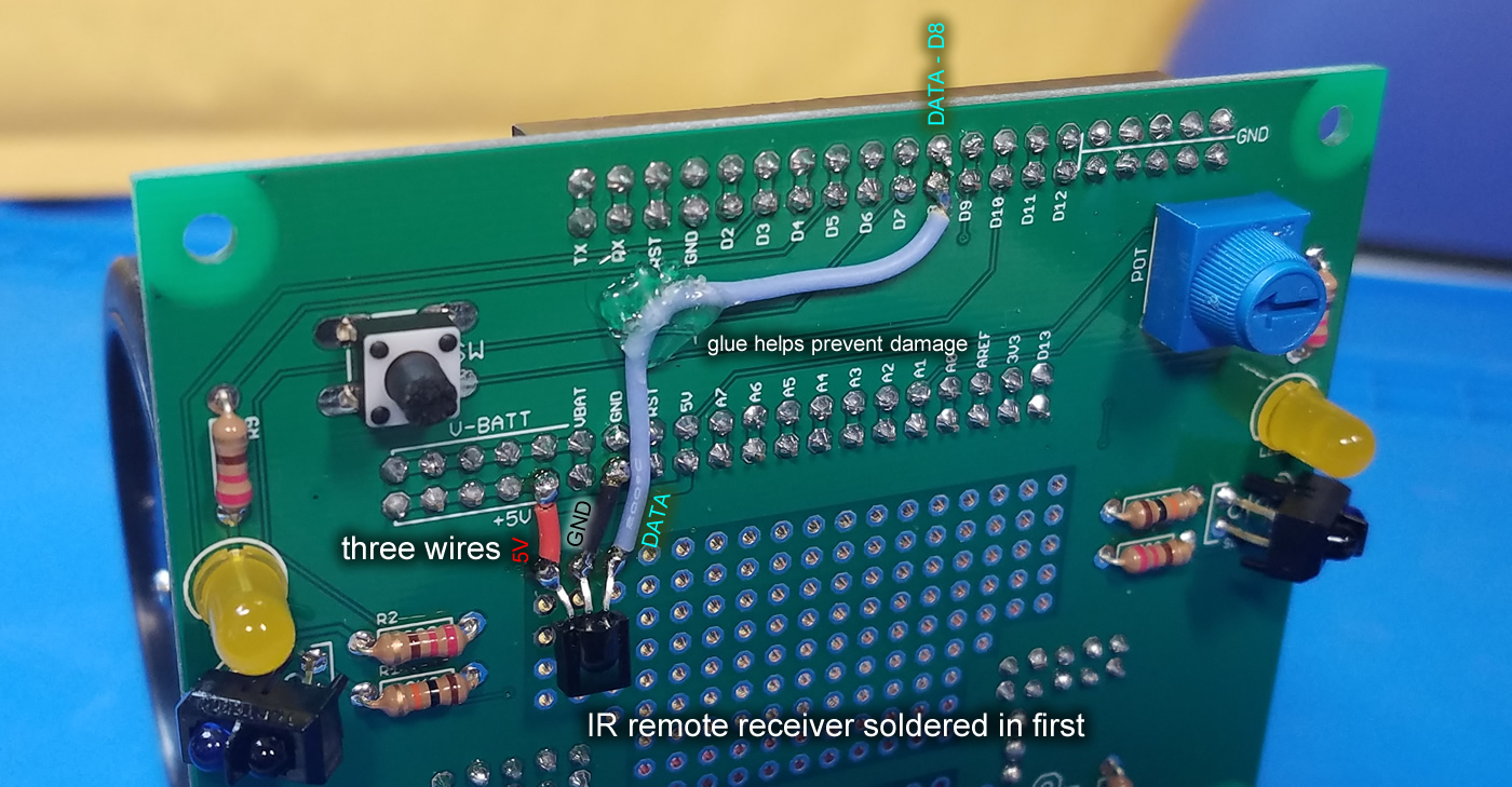
To help you understand, I have made a video on how to solder wires between points. Basically, make sure the solder joint has a lot of solder first, melt that solder and then stick in the wire's exposed end.
Also notice in the picture, all the solder joints and all the wires are soldered from the front side. There's no real rule that tells you which side you should use, in this case, it's easier to use the front so that's what we did. Get creative when you need to, if you are not sure if it will work, first, think about "what could go wrong?", and also... just try it out and see if it works, as long as nobody is going to get hurt.
Now the IR remote receiver is a permanent part of your robot!
Afterword
You now know how to use a solderless breadboard, and you have a robot that can supply power and signals to any circuit you build using the breadboard. Breadboards are great because they save you money, since you can always re-use the parts you plug into it. But remember that the parts might accidentally pop out of a breadboard if you are not careful.
You also know how to use a perfboard prototyping circuit board, when you need to make a circuit that is more durable than a breadboard. I also taught you how to desolder in the previous class, so you know how to both add components and remove components when you use a perfboard.
If you ever need to build a big circuit, people do sell bigger breadboards, and you can actually connect breadboards together like lego bricks. Perfboards are available in all sizes and you can cut them if you have a saw or other cutting tool. Perfboards are dirt cheap.
Homework
Why not add more functions to your robot that can be activated by other buttons of your TV remote controller? All you need to do is read more command codes.
Then, find some cool parts you want to attach to your robot. Perhaps you want to put a LCD screen on your robot and be able to display text? Maybe use a servo to give it a head that can look around? How about a tiny speaker so you can make some noise?
Your robot has IR emitting LEDs, now that you can debug what your own TV remote is sending, do you think you can make your robot automatically control your TV? Try making your TV change channels every 5 seconds. (there is a lesson on this, click here)
If you need more pins and don't need the stuff that's already built into the robot, you can remove the Arduino Nano and place it into a breadboard. This will allow you to do even bigger projects.
