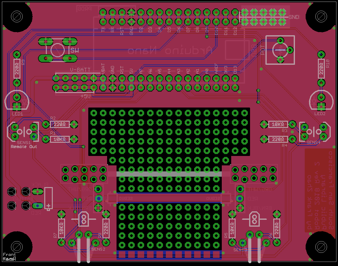
Our Robot's Circuit
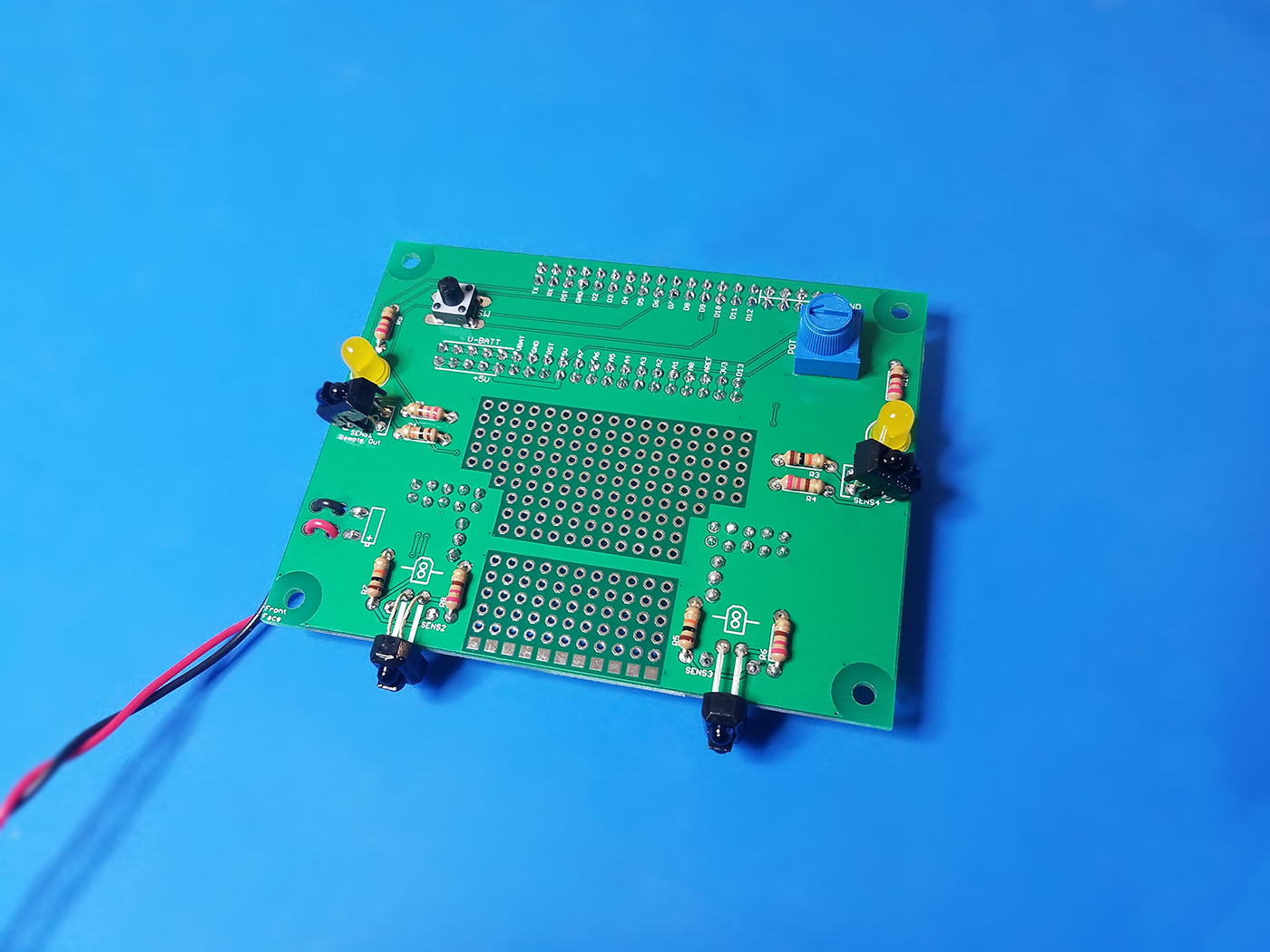
This is what our finished circuit board looks like, with all the sensors, resistors, LEDs, etc. After you understand how it works through reading this lesson, the next class will give you the parts you need and teach you how to solder it together.
Reading a Circuit Diagram
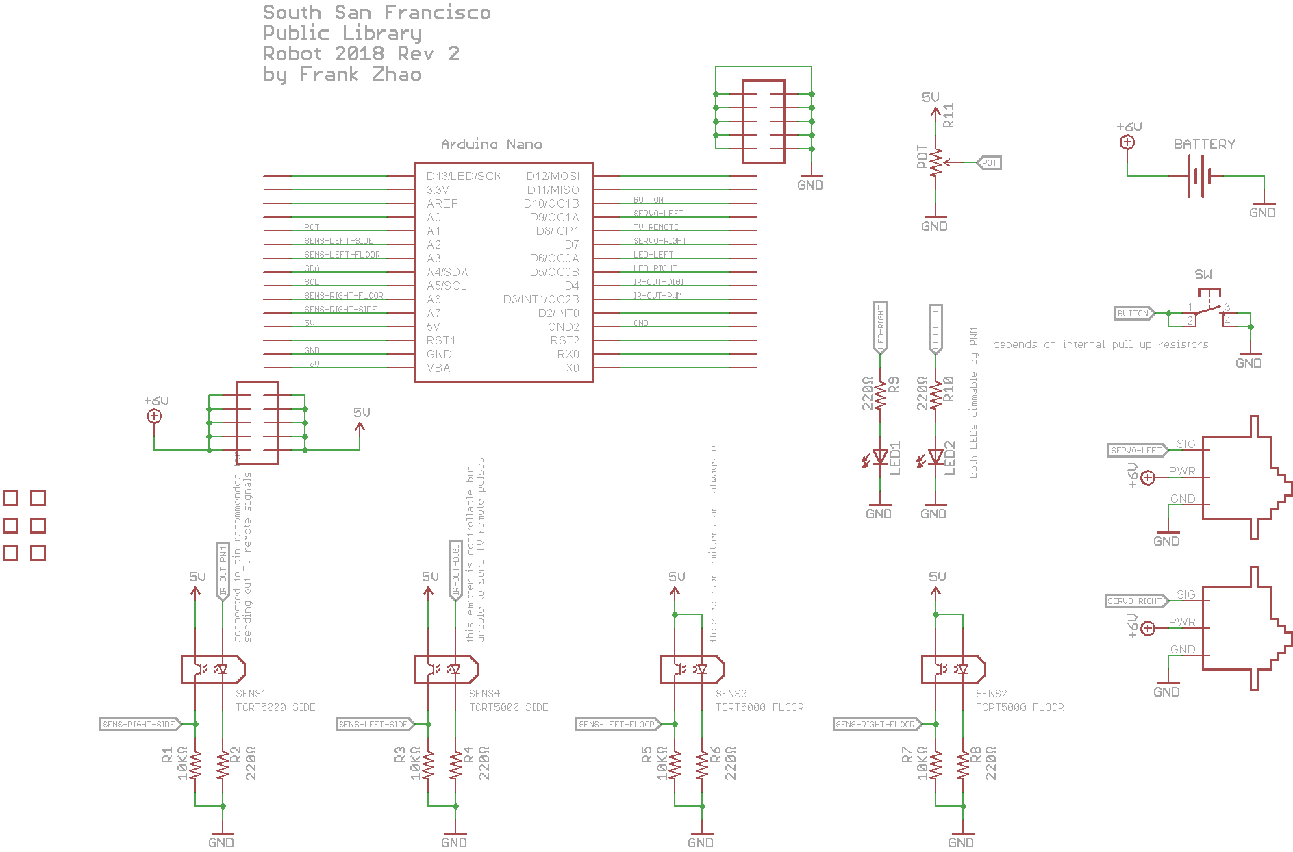
A circuit diagram is a drawing that has symbols and lines in it to show how components are connected in a circuit. Here below I will show you the circuit diagram of our robot:
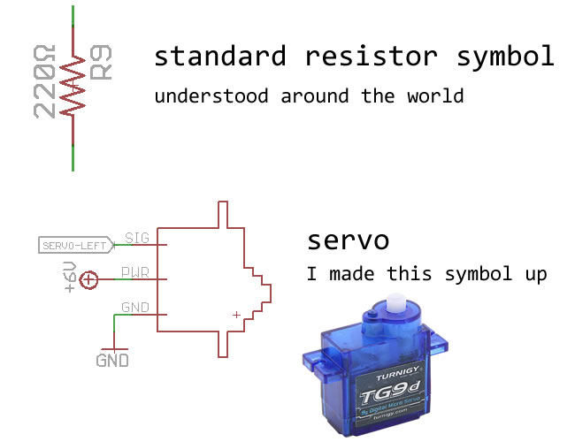
Some common components have a specific symbol to represent them. For example, resistors are usually zig-zag lines.
But sometimes there is no standardized symbol for a part you are using, so you can make it up, or even just draw a rectangle and give it a label.
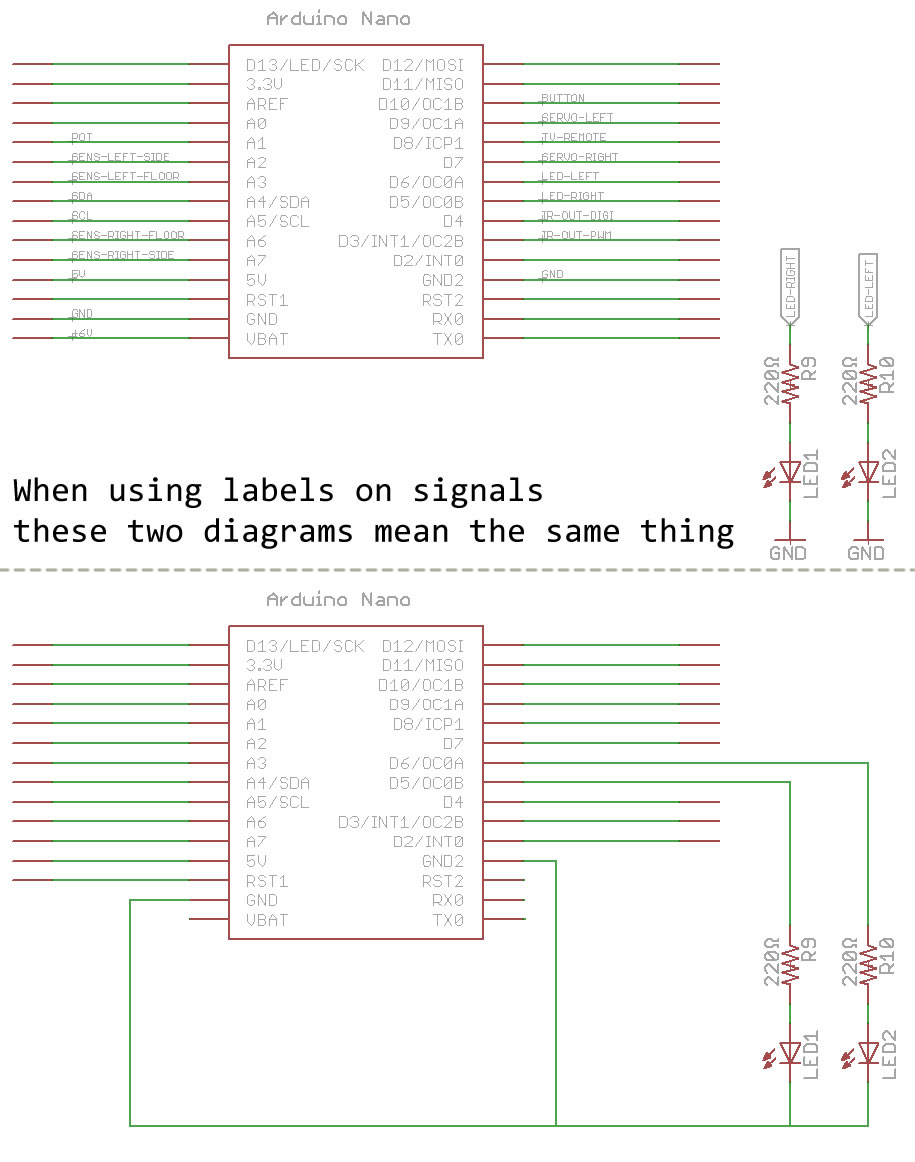
To keep things neat, we can label connections instead of drawing a really long line to represent a connection.
SparkFun has their own page about reading circuits, it is more in-depth. You do not have to memorize circuit symbols right now but their page does list a lot of symbols.
Brains
Our robot's brain is an Arduino Nano, which is a circuit board that contains a microcontroller and some other tiny parts to help it work.
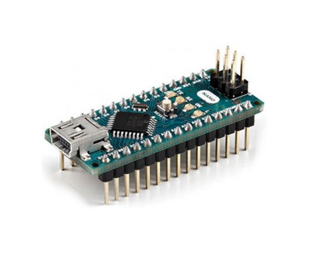
A microcontroller is a tiny computer built into a single microchip. This microchip contains a CPU, memory, and pins. The CPU follows instructions that are stored in the memory and does calculations. The memory is split between storing instructions and storing data. The pins allow the microcontroller to read signals and output signals, allowing it to do things and talk with other circuits.
When you use the Arduino IDE software to write code, a compiler turns your code into the instructions for the microcontroller, and then it is written to the microcontroller's memory through some sort of cable.
Power Supply
There are two major characteristic of electricity: voltage and current. Think of voltage as "pressure", and think of current as "flow".
Electricity flows from positive to negative, but only when there is a complete path (hence the word circuit, which means a complete loop). This path is what we mean when we say circuit. If the path is disconnected in any place along the path, electricity at all points along that path stops moving, this is what we mean if we say "the circuit is open". Here's an interactive circuit where you can open and close switches (click on the switches) to see where the electricity will flow:

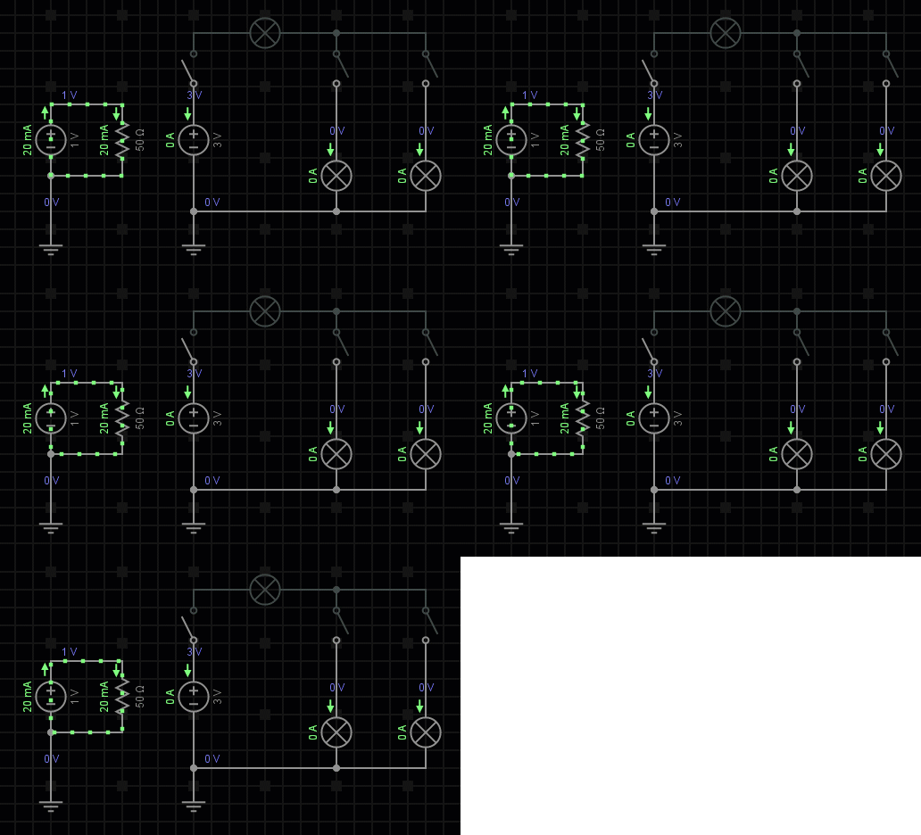
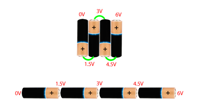
Your robot uses 4 batteries in series as the power supply. Each battery gives around 1.5 volts. This means your total voltage is about 6 volts. Thus, we consider the positive terminal of the whole battery pack to be 6 volts, and the negative terminal of the whole battery pack to be 0 volts.
(When you see "GND" in the schematic, it means ground, which almost always mean 0 volts.)
When you use the batteries, you drain its power, the voltage will go lower. This is bad for sensors, most sensors need a steady voltage that does not change.
Your robot has an Arduino on it. One part on the Arduino is a voltage regulator. When you give it 6 volts, it outputs 5 volts. When you give it 7 volts, it still outputs 5 volts. (by the way, if you give it something lower than 5 volts, it stops working correctly, 4 volts in means 3 volts out)
Any component or circuit that needs a steady voltage is usually connected to some type of voltage regulator.
The voltage regulator on the Arduino is small. It cannot pass a lot of current. Motors need a lot of current and do not need a steady voltage to work. We can connect the motors to the batteries directly.
SparkFun has their own page about powering circuits, it covers additional math around battery capacity, Ohm's Law, and various connectors.
LEDs
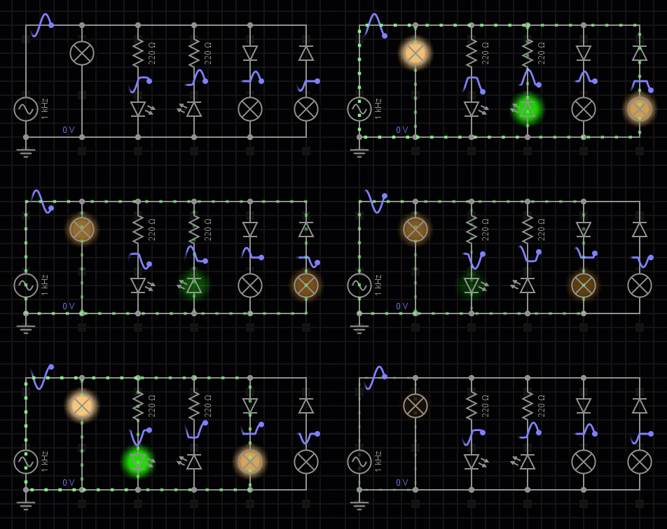
We have many LEDs (Wikipedia page) in our circuits. LED means Light Emitting Diode. A diode is something that electricity can only flow one way through. So "light emitting" means if the electricity is flowing through the diode in the correct way, it will light up. If you connect a diode backwards, it will block the flow of electricity (and a backwards LED will not light up).
The following animation shows a circuit where the current flows forward and then backwards. Pay attention to how the diodes or light emitting diodes block the flow of electric current.
When you connect a LED in a circuit, you need something to control the amount of current flowing through it, or else it could get too hot and burn. To do this easily, we add a resistor into the path of the flow. A resistor is like a very narrow water pipe, the higher the resistance, the tighter the pipe, the lower the flow.
(resistors have a resistance value, the unit is called "ohm", and the symbol is Ω, more Ω means less current)
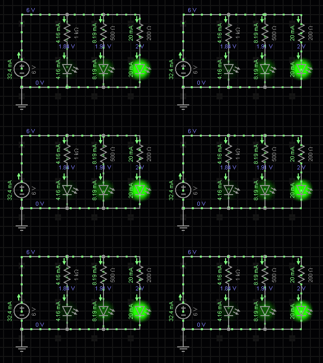
The following animation shows how higher resistance leads to less current, and thus a dimmer LED. A lower resistance leads to more current and thus a brighter LED.
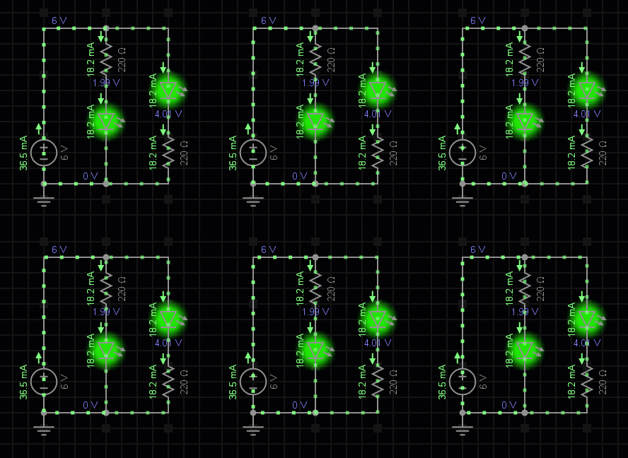
For lighting up a LED, it doesn't matter if the resistor is before or after the LED. The following animation shows how the resistor's location doesn't affect how the LED behaves.
Infrared Sensor
Our sensors on the bottom and the side of the robot are infrared sensors. The official part number for this sensor is TCRT5000L.
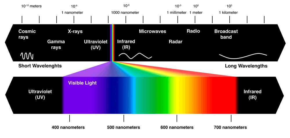
Infrared light is a colour of light that humans cannot see. People often abbreviate it as IR. Think of IR as a colour that is so red that humans cannot see it (some animals can see IR though).
Each sensor we use is actually two parts built into one: a LED that shines infrared light, and a phototransistor that receives infrared light.
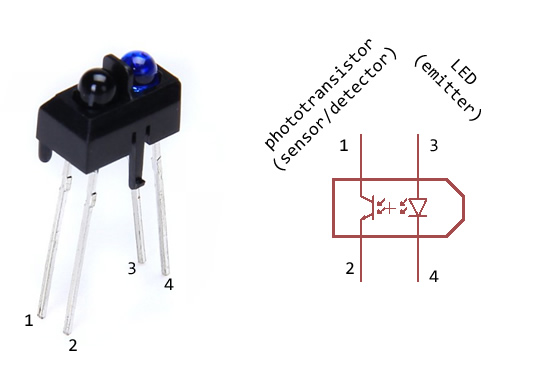
A phototransistor changes the amount of current flowing through it, like a resistor that can change resistance. When it senses more infrared light, there's more current flowing. This means we can see how close an object is or how reflective an object is depending on how much current is flowing through the phototransistor, when we shine infrared light on that object.
It's not easy to measure current. It is easy to measure voltage. This is why a lot of sensors output a voltage that can change according to what it is sensing, because it is easy to measure voltage.
But a phototransistor changes current, not voltage, how can we measure the infrared light?
Voltage Divider
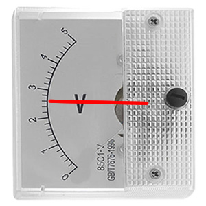
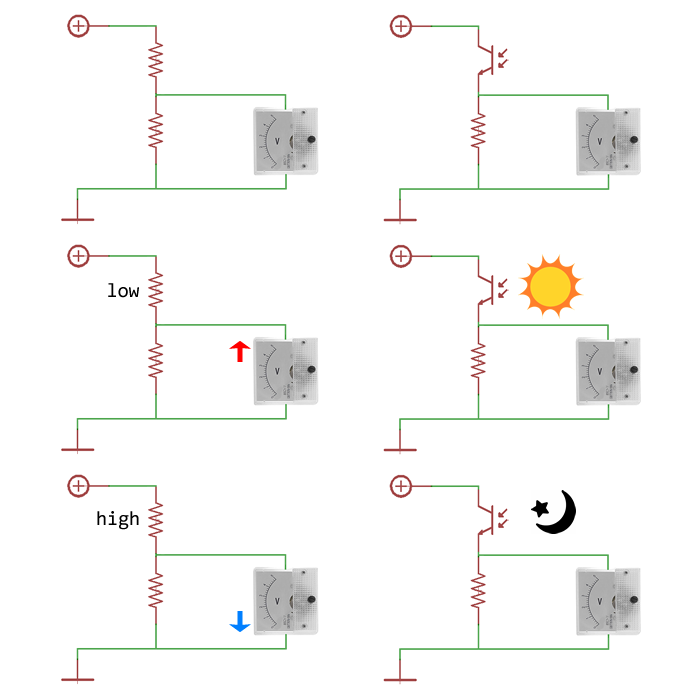
There is a circuit known as a voltage divider. It is usually made of two resistors connected together in series. One of the ends is connected to a voltage, like our 5 volt output. The other end is connected to our batteries negative terminal, which is 0 volts. The voltage in between the two resistors can be measured, and it will change depending on which resistor has more resistance than the other.
Here is an interactive example of a voltage divider.
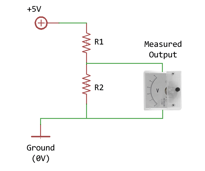
Drag around the slider knobs to change the resistor values, and see what happens to the output voltage.
Output
Voltage:
Like I said before, the phototransistor is like a resistor that changes resistance depending the amount of infrared light it receives. So we can replace one resistor in a voltage divider and get a voltage that is higher when the infrared light is bright and a lower voltage when the infrared light is dark.
Potentiometer
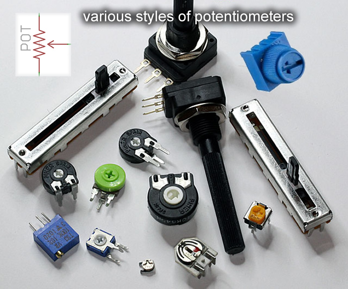
Our robot also has a potentiometer, which has a knob that you can twist. A potentiometer is like a single resistor that you choose where you can split in two. This means it becomes a voltage divider where the output voltage changes depending on where you pick to split the resistor. This means if you turn the knob, you change the voltage it outputs.
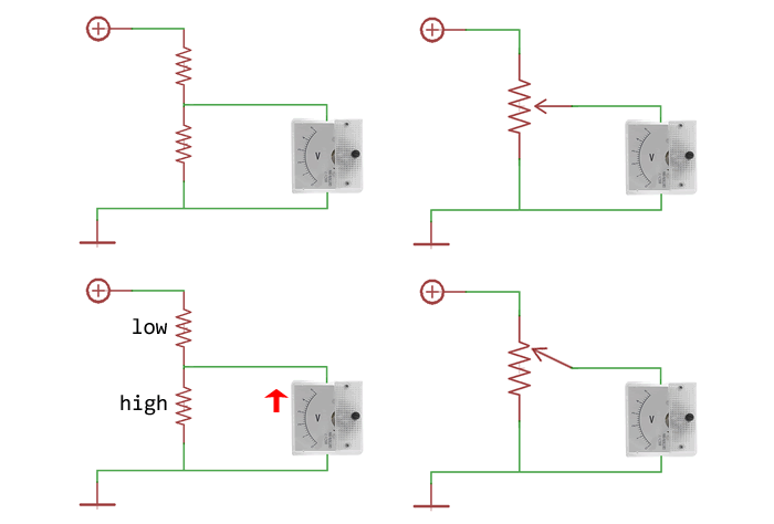
Sometimes, potentiometers are used like volume knobs, and in our robot, you can choose to use it for whatever you want. You can use it to choose how fast it moves, how fast it turns, or something like that. Or a really great idea for your robot is to use it to set a brightness threshold for your sensors. You can tell the robot that, if the floor sensor voltage is more than the potentiometer voltage, then the floor is considered white, and if the floor sensor voltage is less than the potentiometer voltage, then the floor is considered black. This way, if we change the black line on the race track to a grey line, you just need to turn the potentiometer to make your robot follow a grey line instead of a black line.
Button Switch
The robot also has a button on it. A button is a switch, when you press it, it makes a connection, and it breaks the connection when you release it.
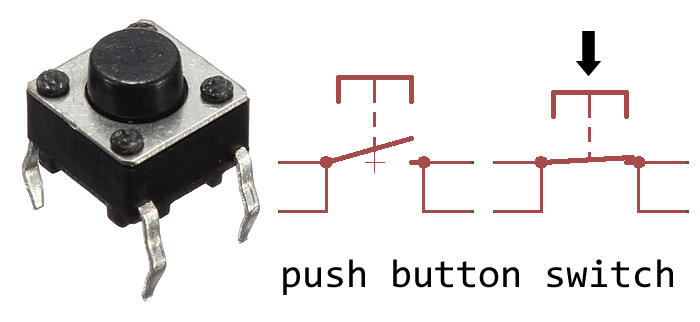
We connect the button between the Arduino, and the negative terminal of the battery (aka ground). Because of the way Arduino is built on the inside, it reads high voltage by default. So when you connect a button to the Arduino and also connect it to ground, it will read high voltage when you do not press the button, and it will read low voltage when you press the button.
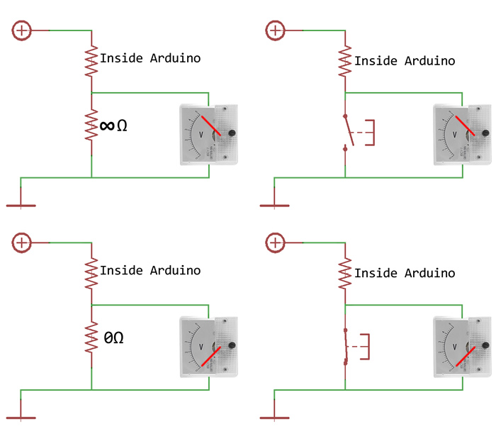
(The resistor inside the Arduino is called the "internal pull-up resistor". The resistance is high, somewhere between 10kΩ and 100kΩ. They are not made very exact because that's difficult to do when they are internal.)
It is a good idea to use the button as a start button for the robot. We do not want the robot to unexpectedly run away when you put the batteries in.
Continuous Rotation Servo Motor
Our robot needs two motors to spin its wheels.
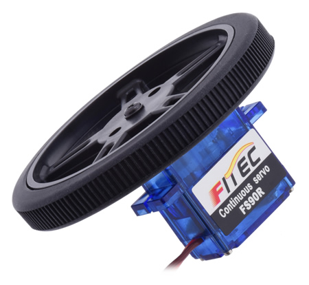
Servos are smart motors. A servo is a motor that you give a command to. A normal servo will go to any angle you tell it to go to, and stay at that angle. A continuous rotation servo will spin at a certain speed that you tell it to spin at.
The difference between a servo motor and a plain motor is that the servo has a built-in smart driver, and a plain motor needs you to connect your own motor driver. This means buying a small servo motor is cheaper than buying both a motor and a driver.
Also, a servo's built-in driver takes less wires on the Arduino to control, in comparison to a motor driver that you can buy. Most servos only need a single wire for the control, then power and ground, meaning 3 wires. A typical motor driver needs two wires for the control, then power and ground, meaning 4 wires.
A servo's control signal is an electrical pulse. The length of the pulse (known as pulse width) determines what the servo does. For a normal standard servo, a pulse that is 1.5 milliseconds long means "go to 0° and stay there", 2 milliseconds means "go to 90° towards the right and stay there", 1 milliseconds means "go to 90° towards the left and stay there". Also, a pulse that is 1.6 milliseconds long means "go to 18° and stay there". The length of the pulses control the servo's angle.
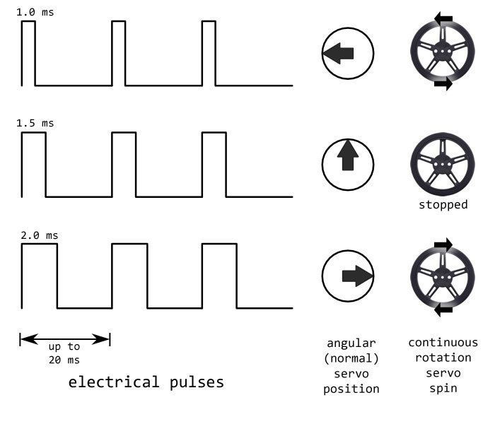
A continuous servo also takes the same electrical pulses as commands. A pulse that is 1.5 milliseconds long means "stop spinning", 2 milliseconds means "spin clockwise", 1 milliseconds means "spin counterclockwise". Also, a pulse that is 1.6 milliseconds long means "spin clockwise but slowly". The length of the pulses control speed and direction.
A video to show you the difference between a standard servo and a continuous rotation servo, and how each one reacts to a command:
For any servo, each pulse means the servo will only do your command for the next 20 milliseconds. This means you need to repeat the pulses at least once every 20 milliseconds, or the servo stops spinning. Don't worry, the Arduino can do this automatically for you.
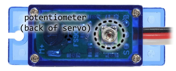
Your Arduino uses a crystal clock to track time so it can send the right pulses, but our servos are really cheap and don't have an accurate crystal clock. When your Arduino sends 1.5 millisecond pulses, your servo might count 1.6 milliseconds, and spin slowly even though you wanted it to stop. If this happens, there's a small adjustment potentiometer on the back of the servo that you can turn with a screwdriver. Send it repeated 1.5 millisecond pulses and turn the potentiometer until the servo stops spinning.
Adafruit has a guide on different motors, servos, and their drivers. SparkFun has a page on servos as well.
What is a Printed Circuit Board?
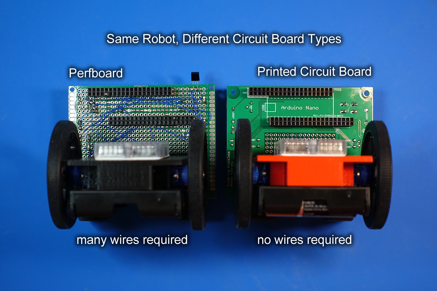
A printed circuit board, or PCB, is a type of circuit board where a fiber-glass (sometimes people use paper too) is covered with a sheet of copper, and then electrical connections are etched into the copper. The connections are called tracks or traces. This means a PCB often requires no wires, just components, which saves a lot of money and time. PCBs are much more durable when there are no loose wires to break. PCBs are also usually smaller, because wires usually take up more room.
PCBs are usually made by one or several robots, so that it is made very precisely. If there are holes that need to be drilled, a robot will do the drilling. The robots can make a lot of PCBs at once but somebody has to program those robots, which takes a while. Thus, usually, if you want to buy just one PCB, it will take 10 days, but if you want 20 PCBs, it will still take 10 days. (remember, it's not just you buying PCBs, there are other people and you have to wait in line)
PCBs look green most of the time because there's a protective coating put on it that is naturally green. Without this coating, circuit boards usually look a bit brown. The robot can also print text onto the PCB to help people understand what component goes where.
PCBs are usually drawn in a PCB layout CAD tool. You need to draw a circuit schematic diagram first, and the PCB layout software will use the schematic to help you, give you hints, and prevent you from making mistakes. Below is a screenshot of what I drew when I designed our robot's PCB, and what the factory made from my drawing.
The difficulty of designing a PCB varies. A child can design a PCB that only has to light up a LED. When you get involved in designing high speed (speed as in data rate), low noise, and high power circuits, then it takes some serious expertise to know how thick and how long each trace must be, and also how close two traces could be next to each other. Our robot certainly does not require the same expertise as a computer motherboard, our robot only uses 2 layers of copper, a laptop motherboard can need a dozen layers with hundreds of traces per layer.
Homework
Footnotes
When you put any sort of transistor and a resistor together like how we did, usually engineers do not call that a voltage divider any more. It simply helps for people to think of them as voltage dividers. They are technically a simple amplifier, it looks very similar to a "common collector amplifier" except it uses a phototransistor instead of a BJT transistor.
Our robotics classes will not be covering how to design a PCB. You should be able to learn this on your own by exploring the internet about this subject. I can certainly help you if you need help. Before attempting to make a PCB, you should already have the skills to design and make circuits on breadboards and perfboards first, which is covered in the extra lesson later. A class on designing PCB is possible but it will have to be a much simpler project than a robot.


