

Voltage, Current, and Resistance
The previous circuit basics class did mention concepts like voltage, current, and resistors, but I didn't fully explain everything yet. I have explained that a greater resistance causes lower current, and I did explain how changing resistances in a voltage divider changes the output voltage of the voltage divider. I will now explain how these two concepts are related, and the math behind them.
First, you need to understand the difference between series and parallel circuits. From the Wikipedia page on this topic: "Components connected in series are connected along a single path, so the same current flows through all of the components. Components connected in parallel are connected along multiple paths, so the same voltage is applied to each component."
In the circuit shown below: The left circuit has two resistors connected in series. The right circuit has two resistors connected in parallel.

In a series circuit, current remains the same through all the components. Think about it, there's no branching path for the electricity to escape, so what goes in one end must come out the other end at the same flow rate. When you have parallel circuits, then there's another path for the electricity to flow, so each branch could have a different current. The following simulation will demonstrate this:

When resistors are placed in series, the total resistance is equal to the sum of all the resistors. In the above animation, you can see that two 100Ω resistors has the same current flowing through it as one 200Ω resistor.
When resistors are placed in parallel, the total current (not total resistance) is equal to to sum of all the current down both branches of the circuit. In the above animation, you can see that two resistors with 2.5mA flowing through them results in the total current being 5mA.
Knowing this, you should be wondering how to calculate current from resistance and voltage. This relationship is called Ohm's Law. From here on, you need to know some math: multiplication, division, and basic algebra.
- Voltage, measured in Volts, abbreviated as V, and symbolized by V in math equations
- Current, measured in Amperes, abbreviated as A, and symbolized by I in math equations
- Resistance, measured in Ohms, abbreviated as Ω, and symbolized by R in math equations
Ohm's Law says that the relationship between voltage, current, and resistance, follows this math equation:
If you use your algebra skills, this also means:
Take a look at the above simulation again. The circuit in the middle, with one resistor of 200Ω, you see that the simulation shows that the current is 5mA (which means 0.005A). The voltage from the power source is set at 1V.
It's that simple.
Now look at the circuit on the top right, the one with two 400Ω resistors. The voltage is 1V. The resulting current is 2.5mA (or 0.0025A).
But the two resistors are in parallel, the total current flowing is 5mA (0.005A). The total current flowing is the sum of all the current through each parallel branch.
How about the circuit on the bottom right? Resistors are 600Ω and 300Ω. The currents are 1.67mA and 3.33mA.
Ah so you should notice that putting two 400Ω resistors in parallel does the same thing as putting just one 200Ω resistor. Putting a 600Ω resistor and a 300Ω resistor in parallel also does the same thing as putting just one 200Ω resistor.
Take a look again, it's the same diagram.
Look at the circuit on the left. It has two 100Ω resistors in series. The total resistance of a series circuit is the sum of all the resistances.
Now we know what is the total resistance, we can calculate the current through the power supply, which is the same as the current through each resistor.
Now think back to what a voltage divider looks like.

... that looks like the previous circuit, just drawn differently, I did add a line between the two resistors to show where the output voltage is being measured. It is measured at 500mV (meaning 0.5V), how can we calculate this?
We know that the total current is 5mA, and one resistor has a resistance of 100Ω. Using Ohm's Law
Awesome, congratulations, you understand how to calculate the output voltage of a voltage divider.
Take a look at the two voltage dividers below, the two resistors have changed but the total resistance have not changed. We can calculate the output voltages for these two.

Shortcut Equations
Voltage Divider Quick Equation
There's a faster way of calculating the output voltage of a voltage divider, which is using the simplified equation after combining all of the above steps. Have a look a the diagram, this time I've put in some labels.

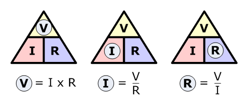
Ohm's Law Triangle
This "triangle" diagram is an easy way to remember how to use Ohm's Law
Using WolframAlpha
WolframAlpha can do these calculations for you even if you don't remember the equations
