

Robot Assembly
Today is the day when we assemble the robot. This is supposed to be a live class that involves soldering and hand tools.
Since we only have a limited time here at the library to use the tools, we shouldn't waste too much time reading. So please read this page before coming to class if you can.
If we do not finish the entire robot today, that's OK. Just come back another day, the tools will always be here at the library.
If you want to do some of this at home, that's great! It will save some time while you are at the library. This requires you to read this entire page first, understand what to do, and understand why you are doing it.
Part List
You should have been provided a pre-packaged kit of parts. If anything is missing, the classroom should have extras. Sometimes, your kit may contain a part that is different from the list, that's OK. Please do not worry about any missing or different parts until you need it (do not ask at the beginning of the class, only ask in the middle of the class).
Tool List
Please do not take any tools home from the library, unless instructed to do so.
- required soldering related tools:
- soldering iron
- solder
- soldering iron stand
- brass wool or wet sponge
- optional soldering related tools:
- desoldering braid/wick
- desoldering pump
- flux
- flux cleaner
- required hand tools:
- phillips screwdriver, #0 size
- wire cutter, or flush cutter, or diagonal cutter
- optional tools:
- needle nose pliers
- wire stripper
- hot melt glue gun
- work mat
Introduction to Soldering
Soldering is easy, and it's easier to learn through pictures and videos than for me to write long boring sentences.


Here is a video:

MightyOhm made this awesome comic about soldering. There is a small version...

... and his long version can be found on his website: https://mightyohm.com/blog/2011/04/soldering-is-easy-comic-book/
(Some instructions might want you to count time during soldering. Don't worry too much about that time too much. The time it takes to heat something up varies with the size of the part, the thickness of the copper, the power of the iron, and a bunch of other things. Usually you will know you've counted too short if the solder doesn't melt, and you can see melted solder eventually make the a shape and stop moving, which means "long enough".)
The long metal legs on a component is also often called leads. You should cut them off after you solder something, but only when you are absolutely sure you haven't made a mistake.
Additional Soldering Tips and Tricks
It's OK to make mistakes! We can fix mistakes, but we can only fix one mistake at a time. Please solder one joint at a time, and then double check that everything is nice and straight. Only do a second joint if the previous joint is perfect.
Enough Talk, Let's Start!
Please pay attention to which side all the components go on.
Soldering: Pin Headers
I want you to start soldering the pin headers first. They are easy to solder and hard to break, so they will give you some good practice before soldering other components.
Doing this first will also make it much easier to solder the Arduino Nano later.
If you have a 10x2 male pin header, cut it into two 5x2 male pin headers first. (if you got two 5x2 male pin headers already, then you don't need to do this)


Solder in all the bigger headers first, with the hints from the previous pictures. These have to be perfectly straight or else you won't be able to plug in your Arduino Nano.


Then move on to soldering the two smaller 3x1 male pin headers. If you have a 6x1 male pin header, cut it in two halves. (otherwise if you have two 3x1 male pin headers, do not cut it)


Soldering: Arduino Nano
With the big female pin socket headers in place, it is really easy to solder male pin headers (two sets of 15x1) into the Arduino Nano. The trick is to use the female pin socket headers to keep the male pin headers straight while you solder.

Soldering: Infrared Sensors (Side)
The drawing on the circuit board shows you how to put in the infrared sensors. Please follow it and do not install the sensors backwards.


Do this for both the left side sensor and the right side sensor.
Soldering Infrared Sensors (Floor)
These two sensors need to have their little extra plastic bits removed, cut them off with your cutters. Do not cut the metal leads.

These two sensors require even more bending. If this is too hard to do with your fingers, then use some needle-nose pliers to help you.


Do this for both the left floor sensor and the right floor sensor.
Soldering: Resistors
Please check the colour codes on the resistor to find out their value. Please place them in the correct locations according to their value.


There are a lot of resistors, four 10kΩ resistors and six 220Ω resistors. Solder all of them in.
Soldering: LEDs
LEDs must be installed in the correct direction. The circuit board shows the LED as a round shape but with a flat side. The LED itself does have a flat side, you have to look really closely or use your fingers to feel the flat side.

Solder in both the left LED and the right LED.
Remember that LEDs are diodes, they only allow electricity to flow in one direction. If you install it in the wrong direction, they will not work.
Soldering: Button and Potentiometer
The button switch and the potentiometer are really easy components to solder. It will be really hard for you to make a mistake here, because the symbols and the positioning of the holes shows you how to insert them. Just make sure you put them in the right place on the right side of the board.

Soldering: Battery Holder
The battery holders should have a red and black wire already, and they should be stripped for you already. If they are not, then use a wire stripper to strip the wires.
You should twist the two wires together. This keeps them neat (there are other advantages too).
There are holes on the circuit board with the label "battery", "red", and "black". The wires snake through the holes without the metal pad, and the exposed end of the wires are soldered to the metal pad.


The "snake" prevents the wire from breaking.
Remember to cut all extra leads from finished solder joints!

Congrats! You have finished the electronics!

Attach the Robot Body
The robot's 3D printed body has tiny grooves on it for the 5x2 male pin headers to slide into. So push the body into the header pins.

Plug in Servos
It's time to plug in the servos into the circuit board. Pay attention to the colours of the wires when you plug in the servo cables into the circuit board. The circuit board is labelled with which colour goes where. (ORG means orange, WHT means white, BLK means black, BRN means brown, RED means red)

Screw in Servos
Place the servos into the robot's body, with the output shaft near the back of the robot. Use the screws (see part list) and a screwdriver to attach the servos to the robot.


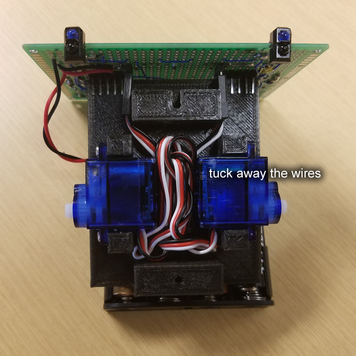
Tuck all the cables away neatly, there's some space between the servos where you can stuff the extra cables.
Screw on Battery Holder
The battery holder is screwed into the bottom of the robot's body using the appropriate screws (see part list). Position it in a way so that the wires are closest to the circuit board (we will tuck the wires away later).
Screw in the side with the round hole first. Screw in the side with the slot second. Otherwise, you might not be able to line up the hole on the holder with the hole on the body.
Tuck away the battery holder wires after the holder is screwed in place.

Screw on Wheels
Put the tires on the wheels if they are not already put together.

Use the tiny screw to attach each wheel to each servo.


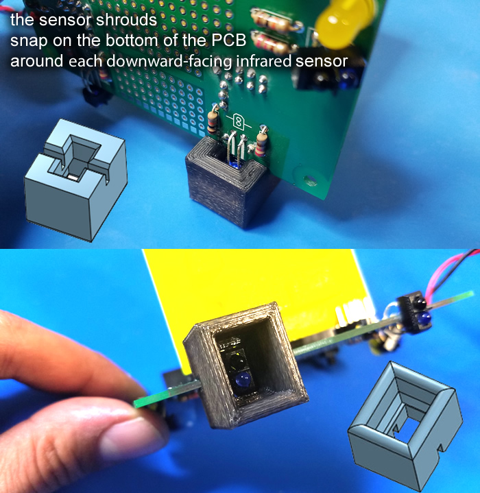
Attaching the Sensor Shrouds
The 3D printed sensor shrouds should snap into the bottom of the circuit board, around the downward-facing infrared sensors.
Congrats! You are Done!

Your robot is finished! But it won't do anything until the Arduino Nano is programmed. Plug the Arduino Nano into your circuit board now. Make sure it is in the correct spot and in the correct orientation. Make sure all the pins are in the right place!

You should also stick the solderless breadboard onto your robot. The back of the breadboard should have a protective sheet over the sticky padding that you need to peel away first.

There's no power switch on this robot, so to stop your batteries from dying, only install the battery when you want to play with the robot, and remove the batteries when you want to turn the robot off.
Testing the robot will be done in the next class, where we learn to use the Arduino Nano.