

Project: Referee
Our little referee is actually your robot with a LCD screen and a laser sensor attached. These parts are dirt cheap and very easy to use with Arduino.
The job of the referee is to time how long it takes for your robot to drive around our race track. It uses a laser beam as the finish line. Sensor detects if the laser beam is broken, and the referee's Arduino will start and start the stopwatch timer when the sensor indicates that the racer has crossed the finish line.
People use Arduinos to make chess timers and such all the time. You can even build score boards for whatever sport you are into.
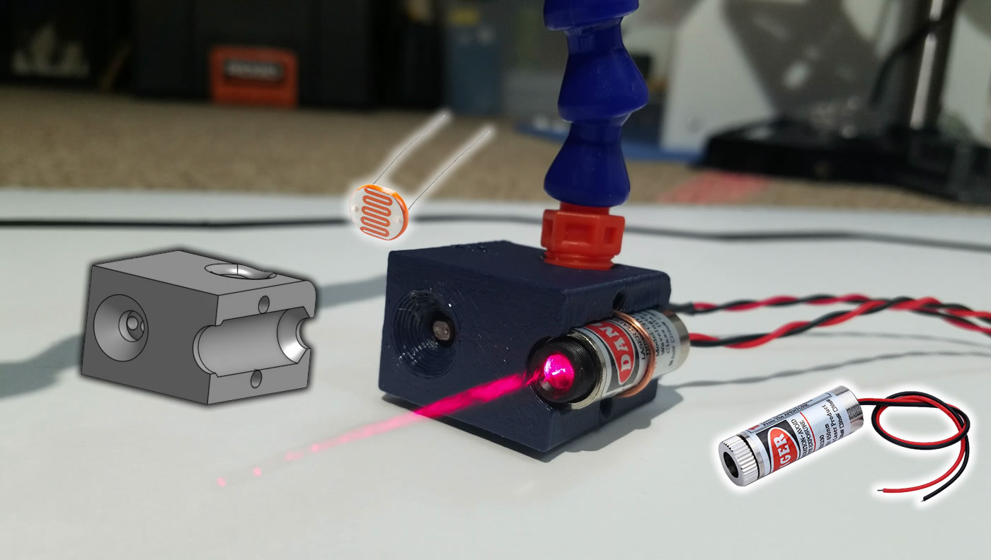
There are essentially three new parts we are using. The laser, the sensor, and the LCD screen. The laser and the sensor are mounted to a gate that I built.
The "Gate"
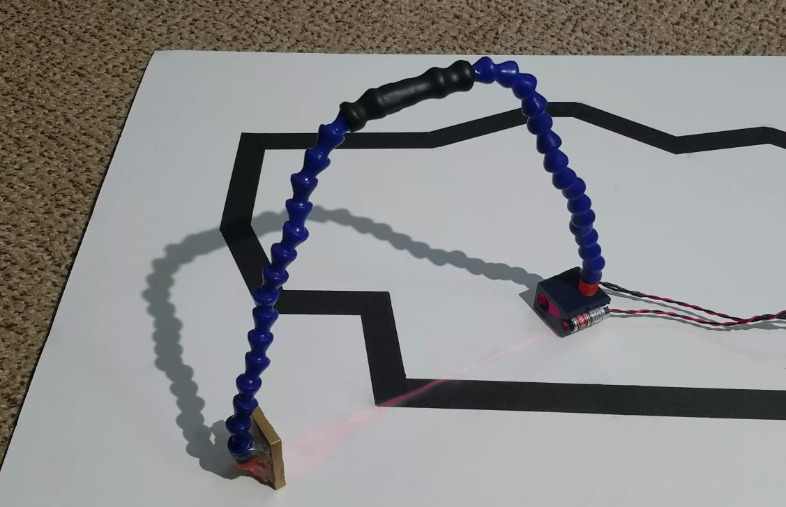
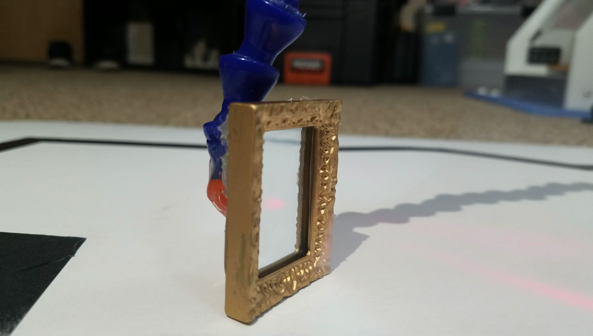
A piece of 3D printed plastic is used to hold the laser pointer and the light sensor. There is an arch made from a flexible hose, and at the other end of the hose is a simple mirror. The mirror is used to bounce the laser beam back into the light sensor.
If you are curious, the 3D model of this gate block: click here
Laser
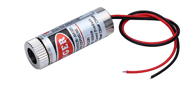
This is an ordinary red laser pointer we are using. It contains a laser diode and a focusing lens. A laser diode is very similar to a LED, but built in a way that emits light coherently (the light waves are "neat"). The focusing lens allows us to adjust how spread out the laser beam is. We could have a very narrow straight beam but that'd be hard to aim at our sensor, so we use the lens to spread the beam a bit to make it easy to aim.
I got this laser pointer off Amazon, they are dirt cheap, and has a power level of 5mW, which is considered safe for people to use as a laser pointer. But do not look directly into the beam because it can still hurt your eyes.
Since we do not need to turn off the laser, we simply connect the black wire to ground and the red wire to our 5V power pins.
Light Sensor
The light sensor is a photoresistor (sometimes called a CdS cell). It means that it is a resistor that is sensitive to light (all visible light, not just infrared). More light means less resistance. It is different from a phototransistor, they are constructed differently, and they behave differently in subtle ways. For our purposes, you don't need to care how they are different.
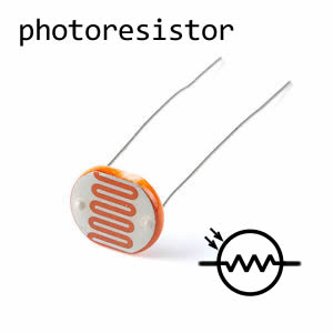
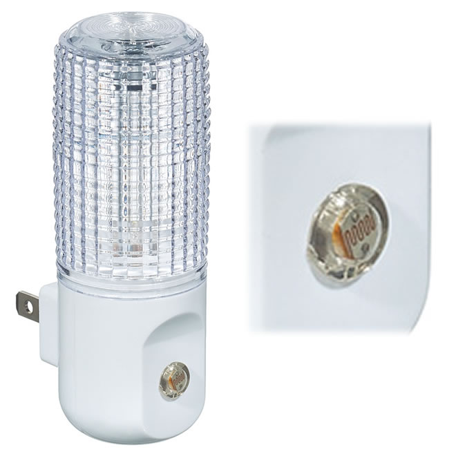
These photoresistors are commonly used in automatic night-lights, and any other lights that turn on automatically when it gets dark. They are insanely cheap.
This sensor is used as one of the two resistors required in a voltage divider circuit. We've learned about this before. The Arduino will use one of its analog input pins to read the voltage divider output.
The resistance of the photoresistor is 10KΩ when it is totally dark. We do not know what the resistance will be when a laser beam hits it, we also do not know how the width and angle of the beam will affect the resistance. This requires testing, but I'm lazy so I simply searched the internet to see what other people use. One of SparkFun's page said that a 5KΩ resistor as the other resistor in the voltage divider should give me a good range of readings.
LCD Screen
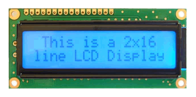
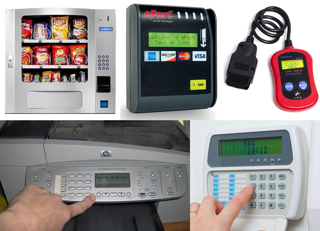
The LCD screen itself is a standard 16 characters wide by 2 lines high display designed for text. These are extremely common in old vending machines, printers, credit card readers, etc.
LCD text displays like these are still popular with hobbyists today because they do not need big microcontrollers and complicated code to work. You can simply use lcd.print("hello"); to make it show text. You do not have to worry about fonts or pixels.
Colour graphical LCD (and even OLED) displays are available and affordable for hobbyists as well but they require a lot of memory and fast data rates to use properly. A lot of them even come with a memory card slot just because their designers know you need to store picture files.
Any sort of display usually uses a lot of pins. Very generally speaking, more pins means more data can be sent, so data can be sent faster, and faster data means faster frame rates on the display. But when you do not have a lot of pins available on your microcontroller, you can buy a LCD display with a backpack attached. This backpack has a microchip on it that converts a 2 wire data bus to a 8 wire data bus. So in the end, you need only 2 pins instead of 8. (total 4 wires, 2 data pins, one for power, one for ground)
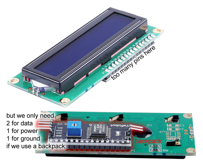
This backpack in particular uses what's called a I2C bus, which uses two wires to communicate (sometimes it is also called TWI, Two Wire Interface). I2C is great since you can connect almost as many devices as you want using only two wires. In the diagram below, your Arduino is a master device, and the backpack is a slave device.
Homework
These are not really "homework questions", it's more of a bunch of things you do when you plan out a project. Feel free to ask me to check over your answers (there are too many correct answers to write down).
- Find where you can buy a 16x2 LCD text display with a I2C backpack.
- What is the Arduino library you need to use the LCD? Does it come with Arduino or do you have to download it separately? If it is on GitHub, what is the GitHub URL?
- Find where you can buy a 10KΩ photoresistor.
- If you can't find a 10KΩ photoresistor, find a 100KΩ photoresistor, and what do you think you should use for the other resistor in the voltage divider?
- The LCD's I2C backpack has 4 pins on its connector. Draw out how you should connect each pin to your robot.
- There is an Arduino function that will "returns the number of milliseconds since the Arduino board began running the current program". What is the name of the function and how do you think you could use it?