Welcome to the 3D CAD Modelling Class

Before Coming to Class

This class will use Onshape. It is a CAD tool that runs in a web browser, and an account is required to use it. It is free to use and similar to many more CAD tools that exist in the professional world.

Please sign up for an account with Onshape before class starts. We do not want to waste time during the class.

Click Here to sign up. You will need an email address, that's all. If the registration process asks weird questions, fill in made-up answers and a fake phone number. Please remember your email and password when you come to class.

Onshape offers a few video tutorials that you can watch, but they are targeted towards a professional audience. You can try to watch these videos, but don't worry if you get a bit confused sometimes. Our own class will be much easier to digest.

Have you used any 3D modelling tools before?

If you have used TinkerCAD or SketchUp, or something similar, please understand that those style of tools are not really professional engineering tools. They are more meant for kids. When you want to make an object that "does something", use a tool meant for mechanical engineering. When you want to make something that "looks good", use a tool meant for artists. If you use the wrong tool for the wrong purposes, you will have a harder time and learn bad habits.

These tools are awesome for engineering: Onshape, SolidWorks, CATIA, Autodesk Inventor, Autodesk Fusion 360, Siemens NX, Solid Edge

These tools are meant for other people: TinkerCAD, SketchUp, Blender, SCAD, OpenSCAD, 3DS Max, Rhino 3D

Onshape and Fusion 360 are both free to use. SolidWorks and Autodesk Inventor are expensive tools but are often given to secondary and post-secondary education organizations. CATIA and Siemens NX are tools meant for designing something as complex as an entire airplane, usually dedicated mechanical engineering curriculums in college will cover these tools.

Foreword

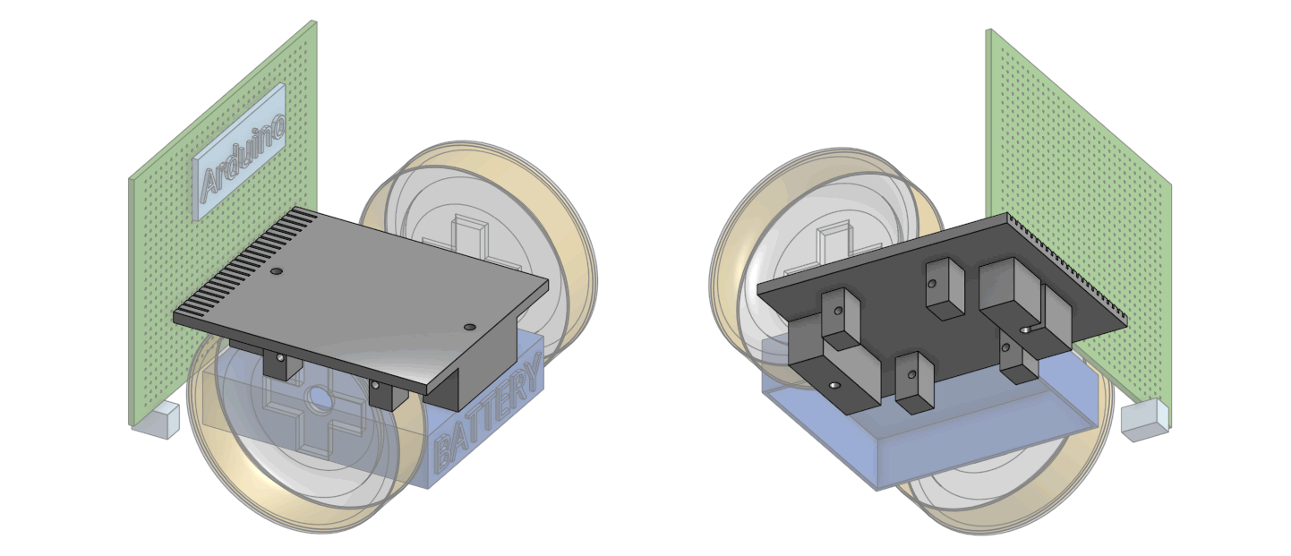
We'll be 3D modelling the body of our robot. It's a simple plate with a few boss features to hold our motors and our batteries. At the end, we will 3D print the model we create.

This class will contain a lot of videos. You should be viewing this lesson in a web browser. View them full screen if you can't see something clearly.

Fixing Mistakes

You might make mistakes, that's OK, everybody makes mistakes. With a computer, you can easily fix any mistakes. Before you ask for help from your instructor, try these things first:

Pressing the ESC key on your keyboard will cancel any current on-going operation.

If you have selected something you didn't want to select, and want to deselect everything, you can try right-clicking somewhere and choosing "Clear Selection" from the menu. Or, just press the spacebar to un-select everything.

Onshape has an undo button, pressing it will revert the last thing you did. The undo button is usually in the top left corner of the screen.

The next video shows you what I mean

Get Started

Please open up Onshape (click here), sign in with your email and password.

IMPORTANT: Set your account to use metric

Our robot is designed with metric measurements (meaning using SI units, like meters and millimeters, not inches). It'll be harder to make a mistake if you switched your Onshape account to use millimeters instead of inches for measurements. Follow the instructions below to change the default measurement units to millimeters:

Create a new document. You can give it any name you like.

If you've never used 3D software before, you need to learn how to use the mouse to rotate, pan, and zoom:

Your First Sketch

Everything starts with a sketch. A sketch can be made on any flat surface or plane. There are three main planes that are always available: top, right, front. We will make the first rectangular block as a sketch on the top plane.

Drawing a rectangle simply involves clicking the rectangle tool on the toolbar, and then starting and ending the rectangle.

Things in your sketch can be given dimensions. We want to make this rectangle exactly 60mm wide and 65mm long. The dimension tool is on the toolbar, then pick the object(s) you want to dimension, pick a place to show the dimension, and finally type in the numbers.

Here are some other ways of dimensioning things.

Turning a Sketch 3 Dimensional

The simplest way to turn a 2D sketch into a 3D solid is to "extrude" it. You can extrude an enclosed sketch (like a rectangle) to a certain length.

Making Changes and Edits

A good CAD tool must allow you to make changes to your model, designs change often and people make mistakes. It's easy to edit a sketch even after you've exited or extruded it, and it is easy to change the parameters of your extrusion as well. Simply right-click on the sketch or extrude operation in the "feature list" (left side of the screen) and then click edit.

What do you mean by "Features"?

In 3D CAD software, a "feature" is a term used to describe almost any part of a model. A sketch is a feature, an extrusion is a feature, just like how your nose is a feature of your face.

On the left side of the screen, you will see a list of features. The order of the features do matter, they are listed in the order in which they are applied/added. Think of the list as a list of instructions for the computer to create your model. You are able to change this order if you need to.

Where is "edit"? I don't see it...

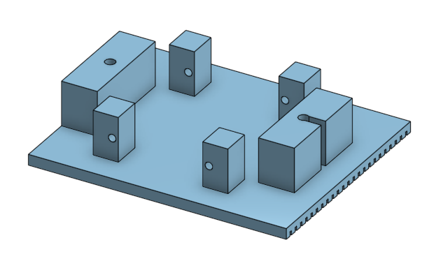
Making Bosses on Your Rectangle

There are 6 little rectangular bosses on the flat rectangular plate. 4 of these are meant to attach your servo motors, and 2 are meant to attach your battery holder. First, start the sketch on top of the flat rectangular plate. Since the design is symmetrical, we can use the "mirror" tool later, this means you should draw some "mirror lines" using the construction line tool.

Draw the rectangles inside this sketch. There are only two to start with, and you'll end up with all 6 after using the mirror function twice.

Now here is the video that teaches you how to use the mirror tool.

Constraints in CAD

A good CAD tool will allow you to add constraints to the objects in your sketches. The constraints in your sketch is a list of rules that the sketch must follow. When you add a dimension to a line, that's actually a constraint, it's a rule that says "this line must be this long".

When the cursor snaps to a midpoint, it means "automatically make a midpoint constraint". A midpoint constraint is a rule that says "this object must always be in the middle of this line, even if the line moves, extends, or shrinks". The "coincident" constraint is also very frequently automatically generated, it simply means "this object must always touch that object".

When you use the mirror tool, that's a mirror constraint being created. When you manipulate one object in the constraint, the mirrored object will also be affected in the same way, but symmetrically about the mirror line.

When you use constraints, you will make less mistakes. For example, if you have a symetrical design, and the things on the left needs to change, without a mirror constraint, you might forget to make the same changes to the right side.

You will see more types of constraints later.

When an object is black, it means you've given the computer enough constraints (rules) to know where the object should be and how big it should be. When an object is blue, it means the computer is not very sure yet, you should add more constraints. You can probably move blue objects by dragging it with your mouse. When something is red, it means you've given rules that the computer can't follow, for example, telling it a line must be 5mm long but also go between two points that are 10mm apart.


Constraints Toolbar

Some students are confused when the constraints toolbar doesn't look like the drop-down list in the videos. Please view this picture to understand:

Double check for mistakes here...

Make sure you don't mess up the orientation of the sketch:

Next we will give the bosses some dimensions. This will also show you how when you move objects on one side of a mirror line, the mirrored objects on the other side will move as well.

How did you know what these dimensions should be?

The bosses should be far apart with a gap to fit the servo motor. When I purchased the servo motor, it came with a drawing telling me exactly how wide it is. If it didn't have a drawing, then I could simply use a ruler or caliper to measure the servo motor first.

The same applies to the battery holder. Look for a drawing, and if you can't find one, then measure it yourself.

Since we are using a good CAD tool and a 3D printer, you can always correct your mistakes later. A lot of times, you might even have to guess and print out different copies with different dimensions and see which one works the best. Do what you have to do to get the job done.

This sketch is done, so now we can use the extrude tool again to turn it 3 dimensional. We make it as high as the servo motors are thick.

House Keeping

When a 3D model becomes more and more complex, it's a good idea to name your features. This way, you and other people can know where to go when there needs to be a change made.

Some really complex models can have hundreds of features. Remember that in a professional situation, you will be working with other people who need to understand your model as well.

Holes: Attaching the Battery Holder

The battery holder has two holes on it, and we will be using screws to attach it to the robot. We will cut holes into the model like we did before.

First start with the sketch of a circle, using center-lines to help you position it exactly. Mirroring is used to create the second circle.

(this video below also shows how to reuse sketches for constraints, in which case, constraints are not added automatically, so you must manually add them)

Finally, use the extrude tool in remove mode to do the cutting. Again, using "through all" instead of a depth.

One of our holes should become a slot shape. This involves making a narrow rectangle and using extrude-remove.

Why are we using a slot shape?

When I was shopping for battery holders, they all look kind of similar, they mostly had two holes you could put screws in. But when I measured the distance between the two holes...

... some manufactures put the holes just slightly closer together, or slightly further apart. This means if we had two holes on our robot, the battery holder might not fit on it because the holes will not line up. By using a slot instead, it could fit more battery holders with different hole spacing.

We used "cut up to surface" mode here instead of specifying a depth. This means the bosses can be made taller or shorter, but the cutting depth will always go right up to the flat plate.

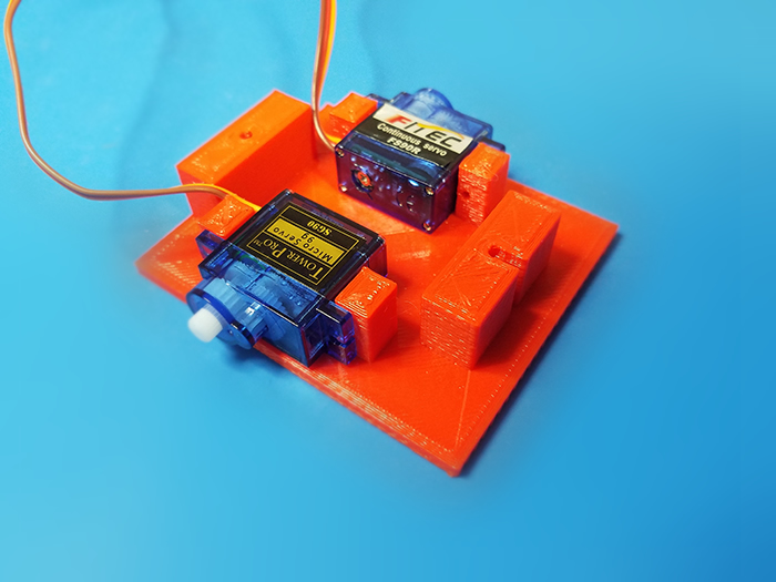
Holes for the Servo Motors

Each servo has two holes on it, and we will be using screws to attach them to the robot. We need to cut holes into the bosses for these screws. This is done by drawing circles on the side of the bosses, and then using the extrude tool in remove mode.

While in remove mode, we can choose "through all", which tells the tool to cut through the entire model, instead of to a certain depth. (this means you can make the model thicker later and still have the hole go all the way through)

Holding the Circuit Board

The front of the robot body has a slight extension that will attach to the circuit board.

This is done in CAD with a simple rectangular sketch followed by an extrude-add operation.

The circuit board attaches to the 3D printed body with some pins, we need to make some slots for these pins in our 3D model. We will start with a thin rectangle in the front of the robot, on the bottom side, where we just made the extension. We center it using constraints made with older sketches.

We need a lot of slots, so this will teach you how to use the pattern tool, so you can make many rectangles from a single rectangle. We make the pattern on one side, and then mirror all of the rectangles created by the pattern.

Finally, the slots are cut into the plate, using the extrude tool in remove mode.

Common mistake during this step

In the very first sketch, you were supposed to make the rectangle 60 mm wide and 65 mm long. Some students accidentally make it 65 mm wide and 60 mm long instead. This is not a big problem until you try to follow the instruction on how to use the linear pattern tool.

Also the linear pattern tool might leave behind some construction lines that might cause you confusion.

So here's a video on how to do this step even if you made the previous mistake.

Congratulations, You Are Finished!

If you did all that, you are finished making your 3D model.

3D Printing

Export the part from Onshape. Give it a name, use STL binary format with millimeter units. After the file is downloaded, use your slicer tool (in our case, Ultimaker Cura) to prepare the GCODE file for printing. Remember to rotate the model so that the flat side is on the bottom. Use 0.2mm or 0.3mm for layer height if possible, with 30% - 50% infill, no support or adhesion should be necessary.

Other 3D Printed Parts

Sensor Shroud

The robot has sensor shrouds that are 3D printed. These shrouds make sure that ambient room lighting and sunlight doesn't disturb the floor sensors. To minimize reflection, black plastic is used, you shouldn't make these out of any other colour.

The 3D model is here: link to Onshape 3D model

Think of this as homework. Try to 3D model this part yourself using Onshape. Since I already made the model, you can actually view all of my sketches and features. Don't worry too much about modelling it out, just go through my model's list of features, and see what each feature is doing.

Wheel

The robot's wheels are purchased from an online store. But if you want to 3D print your own wheels, you can! I have made an example of a wheel design already. It uses rubber bands as tires.

The 3D model is here: link to Onshape 3D model

I did make a mini-video on how this model was made:

Think of this as homework. Try to 3D model this part yourself using Onshape. Since I already made the model, you can actually view all of my sketches and features. Don't worry too much about modelling it out, just go through my model's list of features, and see what each feature is doing.

If you do finish making this wheel, then you need the X shaped white part (called a "servo horn", which you should be given a few later), and some super glue (super glue, gorilla glue, plastic cement, or epoxy, these are the only glues that are strong enough).

Does this wheel work better than the standard one? I have no idea... You can think about the advantages and disadvantages for homework. (it is wider, what does that mean?)

Try to start your own 3D printing project. Try out what all of the tools do. Make your own 3D models and come to the library to 3D print them. With more practice you'll be able to do more amazing things, and learning CAD is essential to being an engineer.

If you need a project idea, I like to think of things that helps you in some way. Maybe a phone stand? They are usually just a J shape with a leg. Maybe you need to protect something? Make a box for it that's the perfect size. Maybe you need to organize stuff? You can make single object with multiple boxes in it.


Click Here, to return to the list of classes